Fixing device for fixing on a recording material a toner image formed on the recording material including a fixing roller and heating and pressing members

a technology of fixing device and recording material, which is applied in the direction of instruments, electrographic process equipment, optics, etc., can solve the problems of difficult removal of recording material

Active Publication Date: 2013-09-10
CANON KK
View PDF22 Cites 15 Cited by
  • Summary
  • Abstract
  • Description
  • Claims
  • Application Information

AI Technical Summary

Benefits of technology

[0009]The present invention has been accomplished in view of the above problems. A principal object of the present invention is to provide a fixing device capable of easily removing a jammed recording material even when a winding jam, such that the recording material is wound about a fixing roller, occurs.
[0015]wherein when the recording material which has been jammed is removed by pulling a trailing end of the recording material in a winding jam state in which a leading end of the recording material has passed through the fixing nip to reach a contact portion between the heating member and the fixing roller, a drawing force F1 for drawing the recording material, toward an upstream side with respect to a rotational direction of the fixing roller, nipped in the fixing nip between the fixing roller in a rest state and the pressing member and a drawing force F2 for drawing the recording material, toward the upstream side with respect to the rotational direction of the fixing roller, nipped between the fixing roller in the rest state and the heating member are set so that the drawing force F2 is not more than the drawing force F1, so as to prevent the fixing roller from being tightened by the recording material.

Problems solved by technology

Further, when the recording material P was broken (torn), the fixing device was placed in some cases in a state in which it was difficult to remove the recording material P.

Method used


Image

  • Fixing device for fixing on a recording material a toner image formed on the recording material including a fixing roller and heating and pressing members
  • Fixing device for fixing on a recording material a toner image formed on the recording material including a fixing roller and heating and pressing members
  • Fixing device for fixing on a recording material a toner image formed on the recording material including a fixing roller and heating and pressing members

Examples


first embodiment

Image Forming Portion

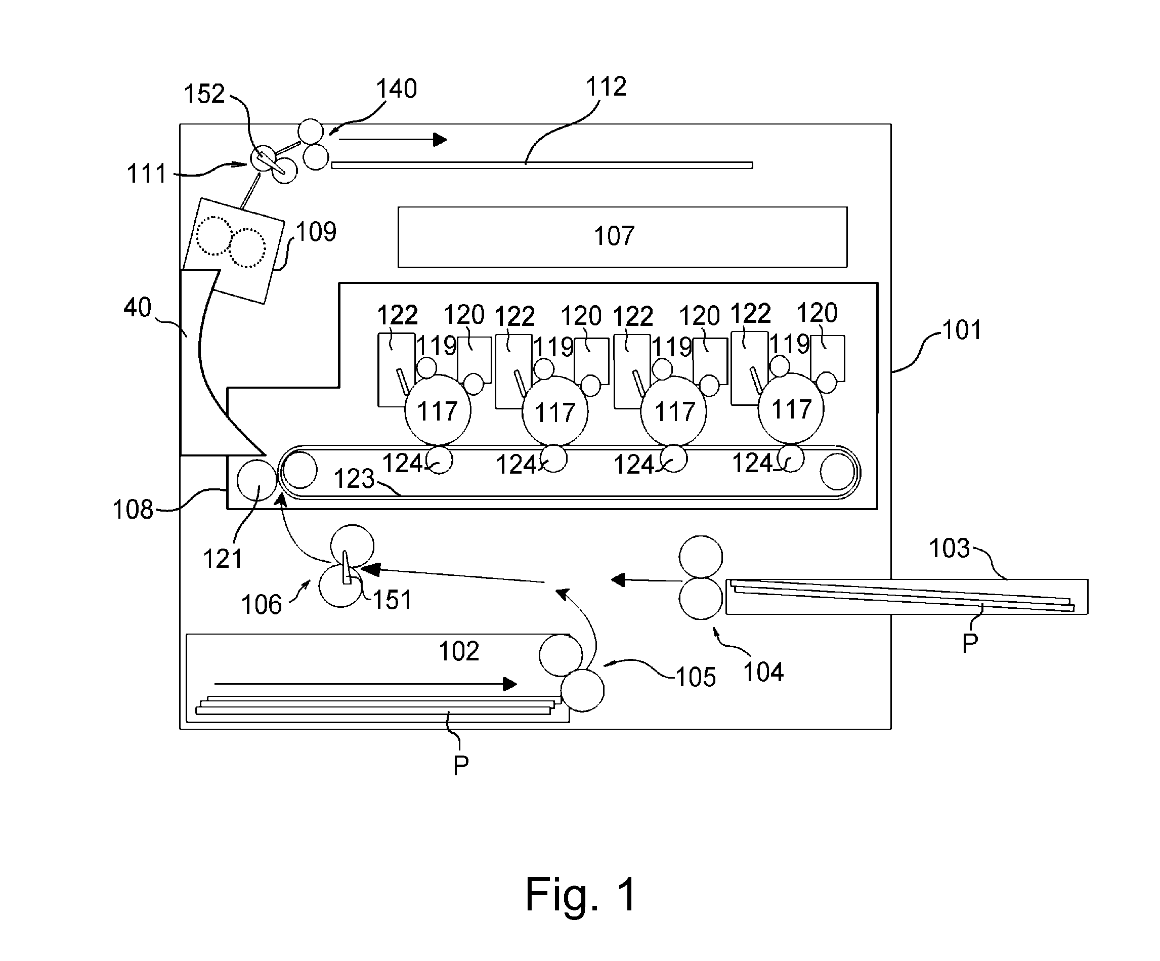
[0027]FIG. 1 is a schematic illustration of an image forming apparatus using an electrophotographic process in First Embodiment of the present invention and shows the case of, e.g., a laser (beam) printer.

[0028]The structure and operation of the image forming apparatus will be described below. A laser printer main assembly 101 as the image forming apparatus includes a sheet feeding cassette 102 for accommodating a recording material P, and the sheet feeding cassette 102 is provided with feeding rollers 105 for feeding the recording material P. Further, the main assembly 101 also includes an externally insertable sheet feeding tray 103 which is provided with feeding rollers 104 for feeding the recording material P.

[0029]On a downstream side of the feeding rollers 105, a registration roller pair 106 for

[0030]synchronization-conveying the recording material P, and a top sensor 151 are provided. A signal detected by the top sensor 151 is transmitted to a CPU 23 desc...

second embodiment

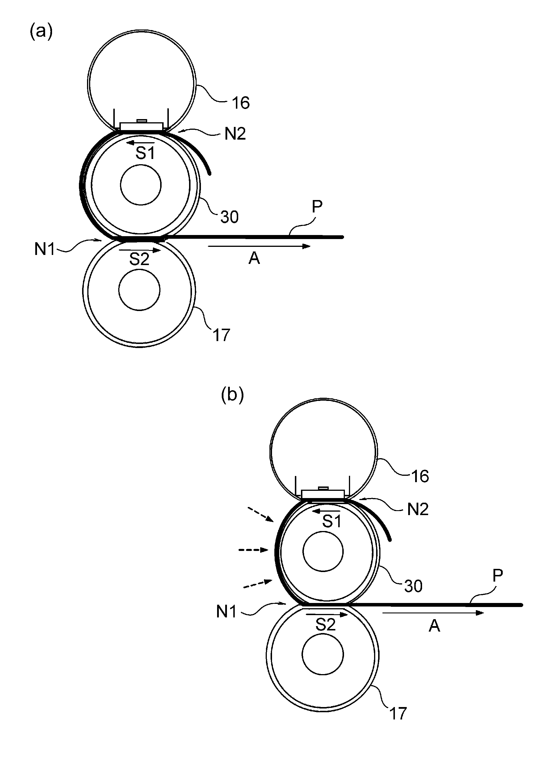
[0085]In this embodiment, a constitution including a pressure-reducing(releasing) mechanism for adjusting press-contact forces of members will be described. Constituent elements similar to those described above are represented by the same reference numerals or symbols and will be omitted from description.

[0086]In this embodiment, the relationship between the first drawing force F1 and the second fixing device F2 during a normal operation is not particularly limited, but a first pressing mechanism 41 and a second pressing mechanism 42 are used as a pressing mechanism including the pressure-reducing mechanism which may be a known mechanism for moving an end of the spring or the like in a pressure reducing (releasing) direction, for example.

[0087]The first pressing mechanism 41 and the second pressing mechanism 42 include the pressure-reducing mechanism which not only increases but also decreases the pressures to the fixing roller 30 and the pressing roller 17. For this reason, the fir...

third embodiment

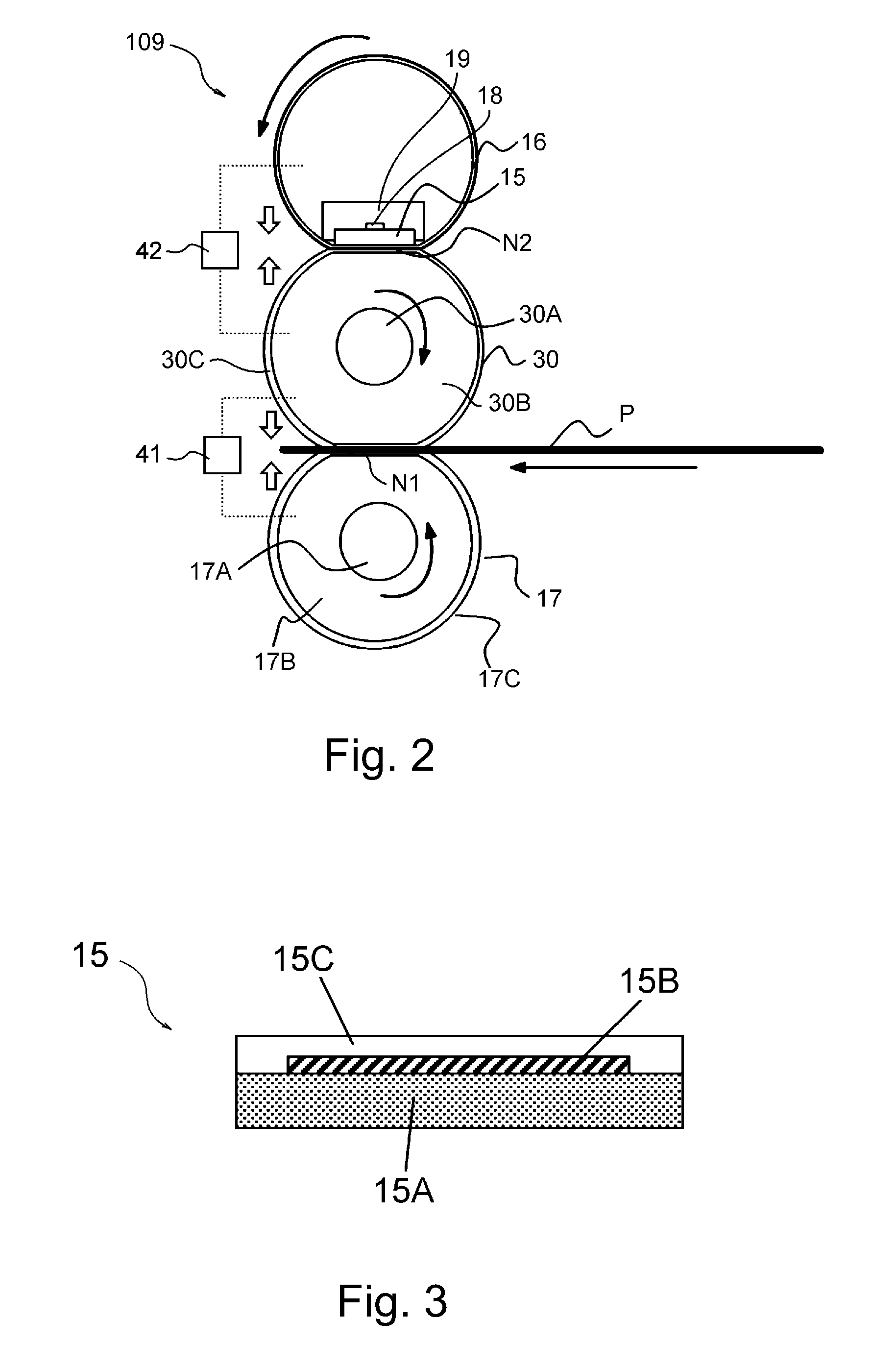
[0091]In this embodiment, a constitution including a pressure-reducing mechanism for adjusting press-contact forces of members will be described. Constituent elements similar to those described above are represented by the same reference numerals or symbols and will be omitted from description. FIG. 8 is a schematic sectional view showing a schematic structure of a fixing device in Third Embodiment.

[0092]In this embodiment, different from First Embodiment, the film 16 is not externally engaged with the ceramic heater 15 but as shown in FIG. 8, the ceramic heater 15 is slidably contacted to the fixing roller 30 directly or via the protective member or the like to form the contact portion N2.

[0093]Specifically, on the protective layer 15C of the ceramic heater 15C, a sliding layer 21D (press-contact member) is formed for the purposes of enhancing the sliding property relative to the fixing roller 30 and of preventing the adherence of the toner. For example, the sliding layer 21D is fo...


PUM


Abstract

A fixing device fixes on a recording material a toner image formed on the recording material and includes a fixing roller, a heating member for heating the fixing roller in contact with an outer surface of the fixing roller, and a pressing member for forming a fixing nip between itself and the fixing roller. When the recording material which has been jammed so that its leading end passes through the fixing nip to reach a contact portion between the heating member and the fixing roller, a force for drawing the recording material upstream when nipped in the fixing nip is at least equal to the drawing force of the recording material, toward the upstream side with respect to the rotational direction of the fixing roller, nipped between the fixing roller in the rest state and the heating member.

Description

FIELD OF THE INVENTION AND RELATED ART[0001]The present invention relates to a fixing device to be mounted in an image forming apparatus, such as printer, a copying machine or a facsimile machine, using electrophotography or electrostatic recording technology.[0002]A heat fixing device as a conventional heat fixing means in the image forming apparatus using an electrophotographic process fixes, on a recording material, an unfixed image (toner image) formed on the recording material by an image forming means, such as an electrophotographic process means. As a fixing type, a heating-roller type using a known halogen heater as a heat source or a film-heating type using a ceramic heater as the heat source has been employed.[0003]Further, in recent years, a fixing device for heating a fixing roller, provided with no heat source therein, from an outer peripheral surface of the fixing roller by bringing a heating member into surface contact with the outer peripheral surface of the fixing r...

Claims


Application Information

Patent Timeline
Patent Type & Authority Patents(United States)
IPC IPC(8): G03G21/00
CPCG03G15/2064G03G2215/00413G03G2215/2019G03G2221/1675G03G21/1638
Inventor NISHIDA, SATOSHIOGAWA, KENICHITANAKA, MASASHITETSUNO, SHUICHIKAN, SHOGO
Owner CANON KK
Why Eureka
Try Eureka