Fusing unit for stable small-sheet feeding in image forming apparatus

a technology of image forming apparatus and fusing unit, which is applied in the direction of electrographic process apparatus, instruments, optics, etc., can solve the problems of large pressure applied to the sheet, large amount of pressure generated in the finishing of the post-fusing sheet, and the sheet plane is not free from large amount of pressure, so as to reduce the cost of structural change.

Inactive Publication Date: 2013-09-10
MURATA MASCH LTD
View PDF8 Cites 4 Cited by
  • Summary
  • Abstract
  • Description
  • Claims
  • Application Information

AI Technical Summary

Benefits of technology

[0011]In order to overcome the problems described above, preferred embodiments of the present invention provide a fusing unit for an image forming apparatus, which can relax a small-size sheet feeding condition to improve a finishing state of the small-size sheet to the same degree as a large-size sheet and stably feed a thin and weak sheet.
[0016]When the position in which the recording sheet is in contact with the first rotatable guide of the first separating pawl is located inside the vertex of the triangle that is defined by the nip portion, the introduction start end, and the lateral feed path, the flexion angles can be separated from each other only by partially changing a structure of the fusing unit. Specifically, the flexion angles of the feed paths can be separated from each other only by changing a position of the central rotatable guide. Accordingly, the structure change that reduces the small-size sheet feeding condition is minimized, and a cost increase associated with the structural change can be reduced. Because the flexion angles of the feed paths can be separated from each other only by changing the position of the central rotatable guide, advantageously the present preferred embodiment can be applied to existing image forming apparatus.
[0017]When the introduction start end of the central sheet discharge guide is located outside the oblique-side portion on the side of the lateral sheet discharge guide of the triangle that is defined by the nip portion, the introduction start end, and the lateral feed path, the feed paths from the nip portion to the rotatable guides can be matched with each other. The same position in the feed direction of the sheet can be guided while deflected by the rotatable guides. Accordingly, the sheet can stably be fed from the nip portion to the rotatable guides, and particularly the thin and weak sheet can properly be fed. Therefore, deformations of the sheet plane such as folding of the corner portion at the start end edge in the feed direction of the sheet and the generation of the wrinkle in the sheet plane, which are caused by the feeding failure, can more securely be eliminated.

Problems solved by technology

However, in the case of a small-size sheet such as a postcard, because the sheet is guided by one or two separating pawls provided in the center in the circumferential surface of the heat roller, a large pressure is applied to the sheet, and sometimes a problem is generated in the finishing of the post-fusing sheet.
Particularly, in the case that a feed path is largely flexed between a nip portion of the fusing unit and the sheet discharge guide, a portion of a length in a feed direction of the small-size sheet such as the postcard is flexed, and thus, a sheet plane is not free from application of a large amount of pressure.
However, in fusing a thin and weak sheet, it is difficult to stably feed the sheet, and there is generated a new problem in that a corner portion at a start end edge in the feed direction of the sheet is folded or a wrinkle.

Method used


Image

  • Fusing unit for stable small-sheet feeding in image forming apparatus
  • Fusing unit for stable small-sheet feeding in image forming apparatus
  • Fusing unit for stable small-sheet feeding in image forming apparatus

Examples


Embodiment Construction

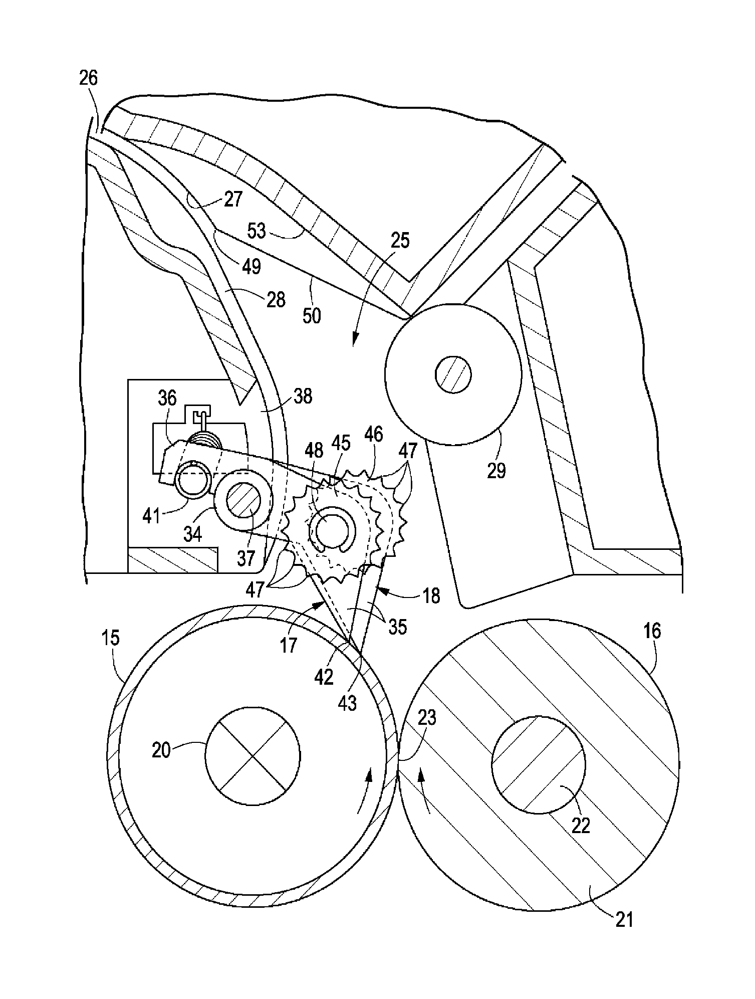
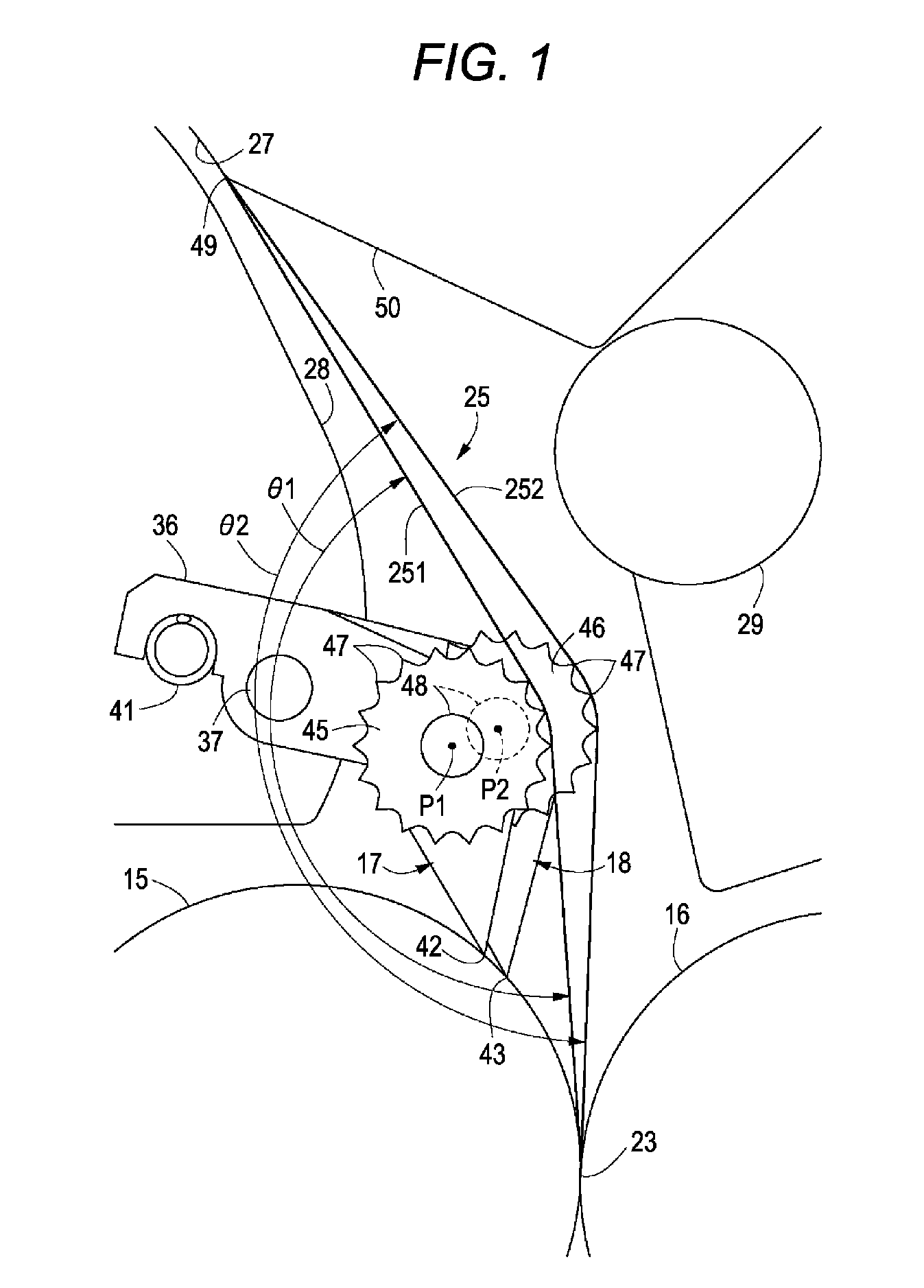
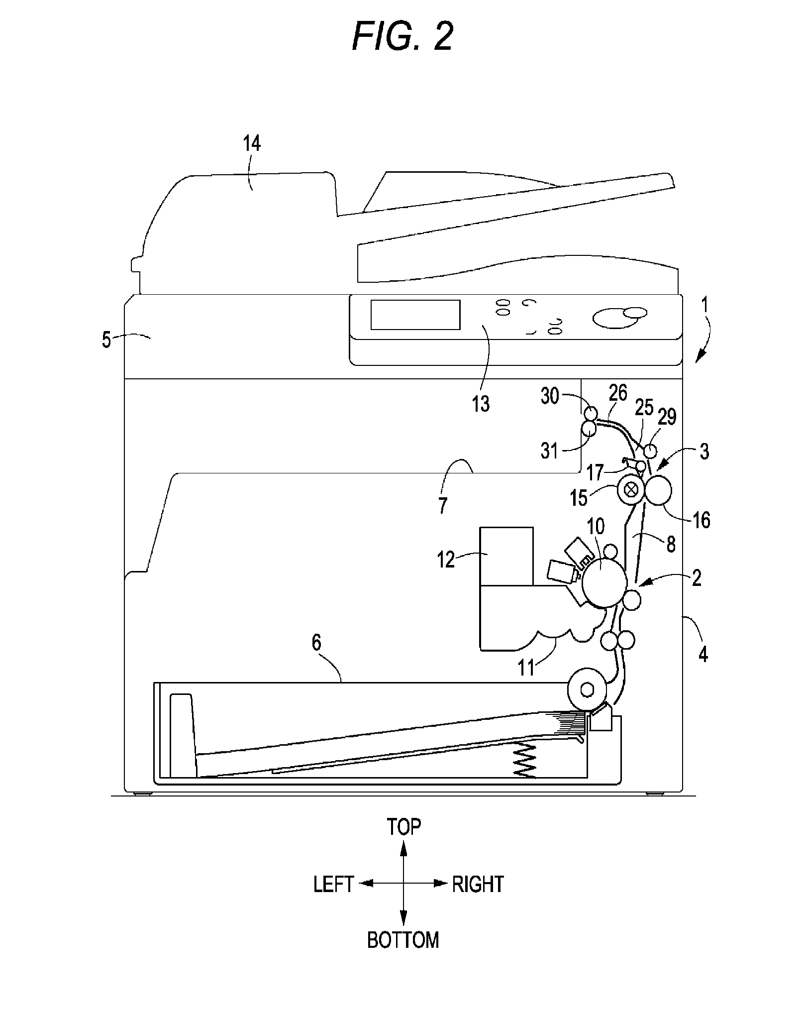
[0027]FIGS. 1 to 5 illustrate a fusing unit according to a first preferred embodiment of the present invention that is preferably applied to a multi-function peripheral (image forming apparatus) having a copy function and a facsimile function. In the drawings, front and rear, right and left, and up and down are subject to cross arrows illustrated in FIGS. 2 and 4 and signs of front and rear, right and left, and up and down expressed near the arrows.

[0028]Referring to FIG. 2, a multi-function peripheral 1 includes an image forming unit 2, a main body unit 4 in which a fusing unit 3 is disposed, and an image reader 5 that is located in an upper portion of the main body unit 4. In the multi-function peripheral 1, a sheet feed path 8 is provided between a paper cassette 6 disposed in a lower portion of the main body unit 4 and an exit unit 7 disposed in the upper portion of the main body unit 4. The image forming unit 2 is disposed below the feed path 8 while the fusing unit 3 is dispos...


PUM


Abstract

A fusing unit includes a heat roller and a press roller, which fuse a toner image fused to a recording sheet; a first separating pawl contacting a circumferential surface of the heat roller and separating the recording sheet from the heat roller; second separating pawls that are spaced from the first separating pawl in an axial direction to contact the circumferential surface of the heat roller and separate the recording sheet from the heat roller; a first rotatable guide in the first separating pawl that guides the recording sheet to a sheet discharge guide of an exit feed path while changing its orientation; a second rotatable guide provided in each of the second separating pawls which guides the recording sheet to a sheet discharge guide of an exit feed path while changing an orientation of the recording sheet; and a fusing feed path that reaches the sheet discharge guide.

Description

[0001]This application claims priority under 35 U.S.C. 119 to Japanese Patent Application No. 2010-246023, filed on Nov. 2, 2010, which application is hereby incorporated by reference in its entirety.BACKGROUND OF THE INVENTION[0002]1. Field of the Invention[0003]The present invention relates to a fusing unit for an image forming apparatus such as a copying machine, a facsimile machine, or a printer, for example, and more particularly to an improvement of a structure of a separating pawl that forcedly separates a sheet from a circumferential surface of a heat roller.[0004]2. Description of the Related Art[0005]In a fusing unit of an image forming apparatus of the related art, the separating pawls are disposed at six points in a circumferential surface of a heat roller. The six separating pawls are constructed by three groups of pairs of separating pawls. In the first group, the separating pawls are disposed at two points on the right and left in the center of the heat roller. In the...

Claims


Application Information

Patent Timeline
Patent Type & Authority Patents(United States)
IPC IPC(8): G03G15/20
CPCG03G15/2028G03G15/2064
Inventor ARAKAWA, OSAMU
Owner MURATA MASCH LTD
Why Eureka
Try Eureka