Electrophoretic display structures

a display structure and electrochromic technology, applied in the field of electrochromic display, can solve the problems of poor whiteness and lack of high quality, and achieve the effect of improving color states

Active Publication Date: 2012-04-10
E INK CORPORATION
View PDF9 Cites 34 Cited by
  • Summary
  • Abstract
  • Description
  • Claims
  • Application Information

AI Technical Summary

Benefits of technology

[0011]The electrophoretic display structures of the present invention may be manufactured by a continuous or semi-continuous roll-to-roll manufacturing process. The structures are capable of providing enhanced color states.

Problems solved by technology

However, poor whiteness and lack of a high quality “black” state are the major problems for reflective color displays using color filters.

Method used


Image

  • Electrophoretic display structures
  • Electrophoretic display structures
  • Electrophoretic display structures

Examples


Embodiment Construction

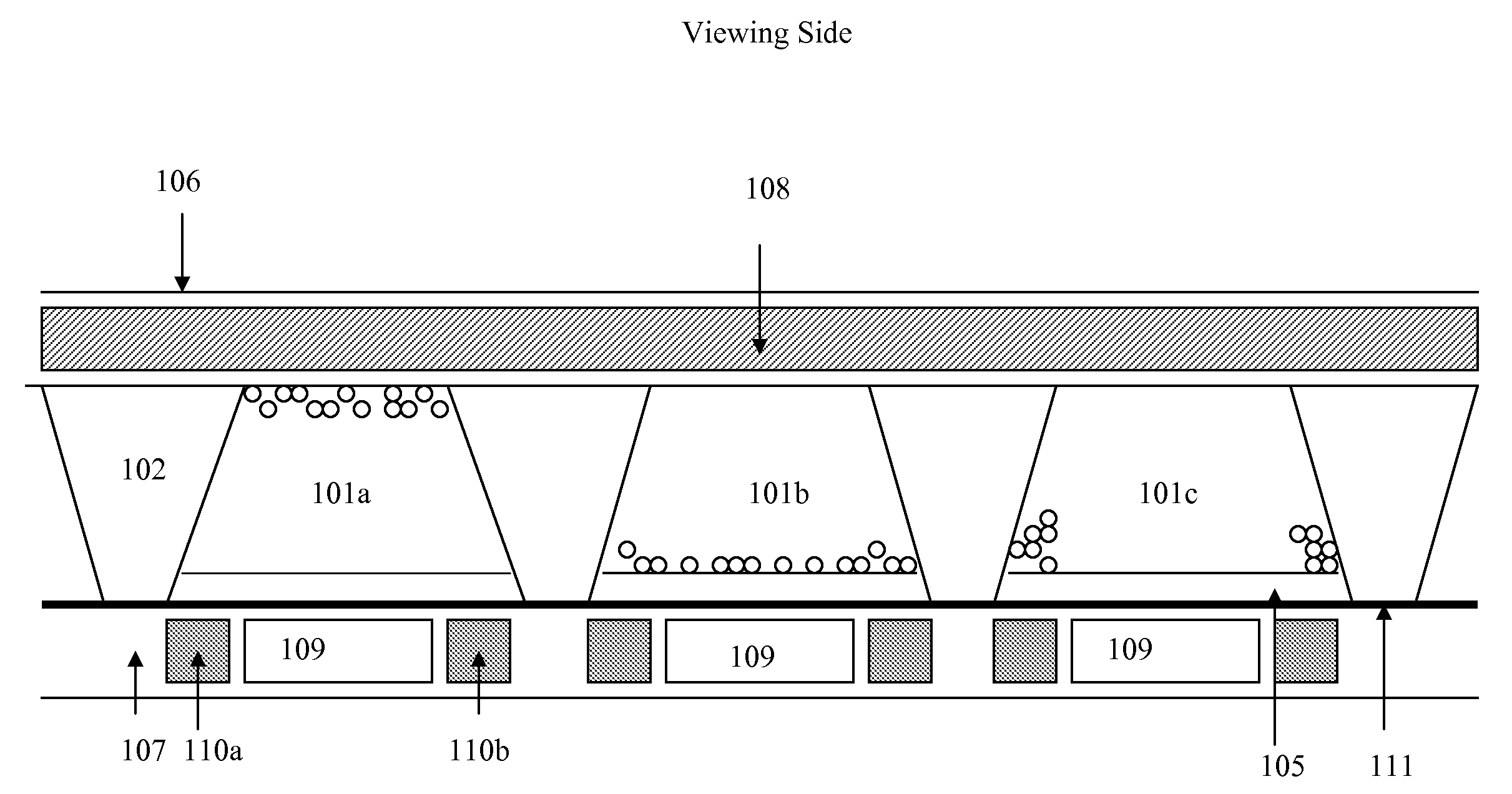
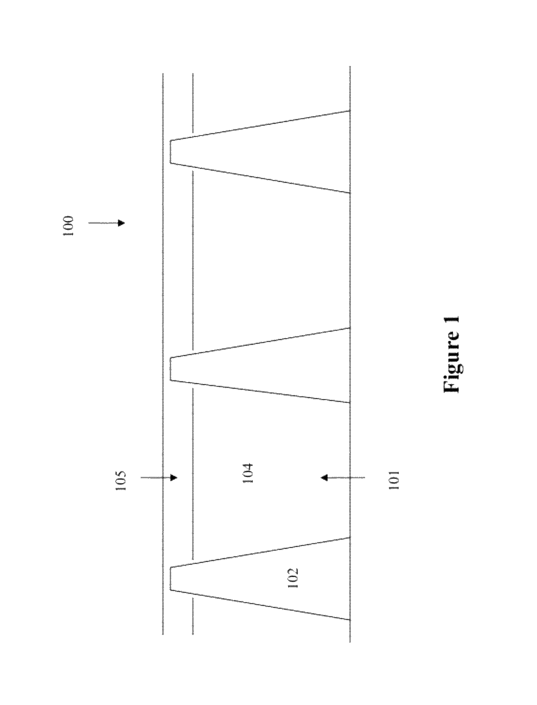
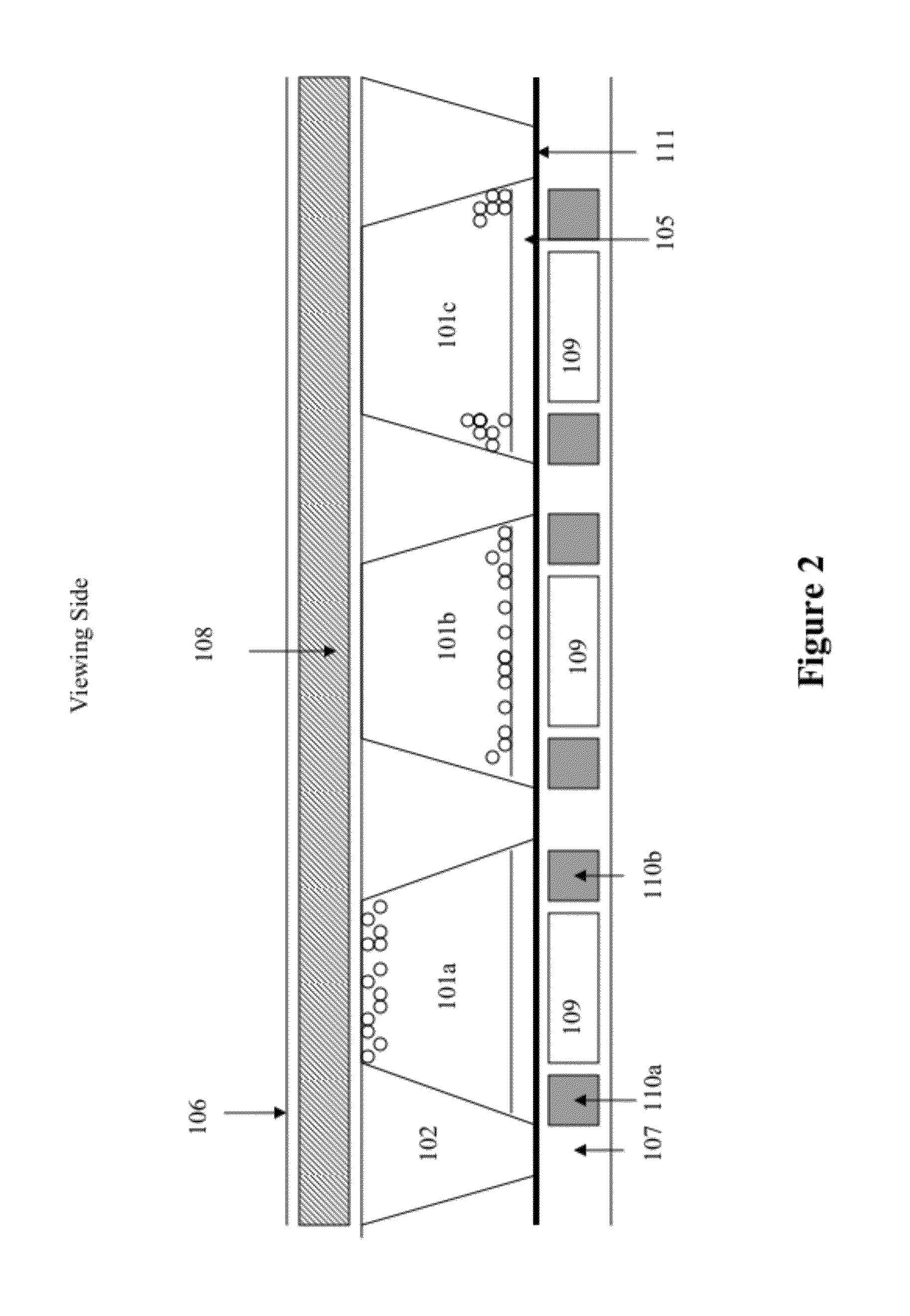
[0025]The first aspect of the present invention is directed to an electrophoretic display structure (100) having trapezoid-shaped partition walls, as shown in FIG. 1. The display cells (or microcups) (101) are separated by the trapezoid-shaped partition walls (102). The trapezoid-shaped partition walls may also be referred to as the slanted partition walls. The display cells are then filled with an electrophoretic fluid (104) and optionally sealed with a polymeric sealing layer (105).

[0026]It is preferable for the slanted partition walls to have an opaque color, especially a gray opaque color. This may be achieved by introducing air pockets or a filler material such as non-conductive carbon black, pigment black, silica, ZnO, TiO2, BaSO4, CaCO3 or polymer particles, preferably non-conductive carbon black or pigment black, preferably in the amount of 0.01-20% by weight, more preferably in the amount of 0.01-10% by weight, into the composition for the formation of the display cells. Co...


PUM

PropertyMeasurementUnit
angleaaaaaaaaaa
angleaaaaaaaaaa
dielectricaaaaaaaaaa

Abstract

This invention relates to a display device comprising a plurality of display cells, wherein said display cells are separated by slanted partition walls. This invention also relates to a display device comprising a plurality of display cells, wherein said display cells are separated by indented partition walls having indented areas. The electrophoretic structures of the present invention may be manufactured by a continuous or semi-continuous roll-to-roll manufacturing process. The structures in which display cells are separated by slanted partition walls or partition walls having indented areas are capable of providing enhanced color states.

Description

[0001]This application claims priority to U.S. Provisional Application No. 61 / 109,154, filed Oct. 28, 2008; the content of which is incorporated herein by reference in its entirety.BACKGROUND[0002]An electrophoretic display (EPD) is a non-emissive device based on the electrophoresis phenomenon influencing charged pigment particles suspended in a solvent. An EPD typically comprises a pair of electrodes, with at least one of the electrodes, typically on the viewing side, being transparent. An electrophoretic fluid composed of a colored dielectric solvent and charged pigment particles dispersed therein is enclosed between the two electrodes.[0003]An improved EPD technology and a roll-to-roll manufacturing process are disclosed in U.S. Pat. No. 6,930,818, the content of which is incorporated herein by reference in its entirety.[0004]For full color displays with the normal up / down switching mode, color filters overlaid on the viewing side of the display may be used. However, poor whitene...

Claims


Application Information

Patent Timeline
Patent Type & Authority Patents(United States)
IPC IPC(8): G02B26/00G09G3/34G03G17/04G02F1/167
CPCG02F1/167G02F2001/1672G02F1/1681
Inventor WANG, XIAOJIASPRAGUE, ROBERT A.KANG, GARY YIH-MING
Owner E INK CORPORATION
Why Eureka
Try Eureka