
Electric vehicle and method of control for active auxiliary battery depletion

a technology of electric vehicles and auxiliary batteries, applied in the direction of engine-driven generators, emergency power supply arrangements, electric devices, etc., can solve the problems of general problems of electric vehicle lost energy, increased loss of energy, and increased energy loss

Active Publication Date: 2013-09-17
FORD GLOBAL TECH LLC
View PDF13 Cites 30 Cited by
  • Summary
  • Abstract
  • Description
  • Claims
  • Application Information

AI Technical Summary

Benefits of technology

[0010]An embodiment of the present invention provides a method. The method includes discharging an auxiliary battery of an electric vehicle while the auxiliary battery has more than a minimum energy. The method further includes preventing a traction battery of the vehicle from charging the auxiliary battery while the auxiliary battery has more than the minimum energy. The method further includes, upon the auxiliary battery having the minimum energy, charging the auxiliary battery with the traction battery to maintain the auxiliary battery at the minimum energy. The method may further include recharging the auxiliary battery and the traction battery via an electric grid.

Problems solved by technology

A problem with the traction battery supplying energy to maintain the auxiliary battery at the fully charged state is that this energy is lost for vehicle propulsion until recovered.
Further, the amount of lost energy can be exacerbated as the auxiliary battery may not always be charged at most efficient operating points.
The lost energy is generally problematic for electric vehicles as efficiency is critical for optimal performance and evaluation.
This is especially a problem for a BEV in that the BEV essentially cannot recover the lost energy until the vehicle is connected to the external electric grid.

Method used


Image

  • Electric vehicle and method of control for active auxiliary battery depletion
  • Electric vehicle and method of control for active auxiliary battery depletion
  • Electric vehicle and method of control for active auxiliary battery depletion

Examples


Embodiment Construction

[0016]Detailed embodiments of the present invention are disclosed herein; however, it is to be understood that the disclosed embodiments are merely exemplary of the present invention that may be embodied in various and alternative forms. The figures are not necessarily to scale, some features may be exaggerated or minimized to show details of particular components. In addition, any or all features from one embodiment may be combined with any other embodiment. Therefore, specific structural and functional details disclosed herein are not to be interpreted as limiting, but merely as a representative basis for the claims and / or as a representative basis for teaching one skilled in the art to variously employ the present invention.

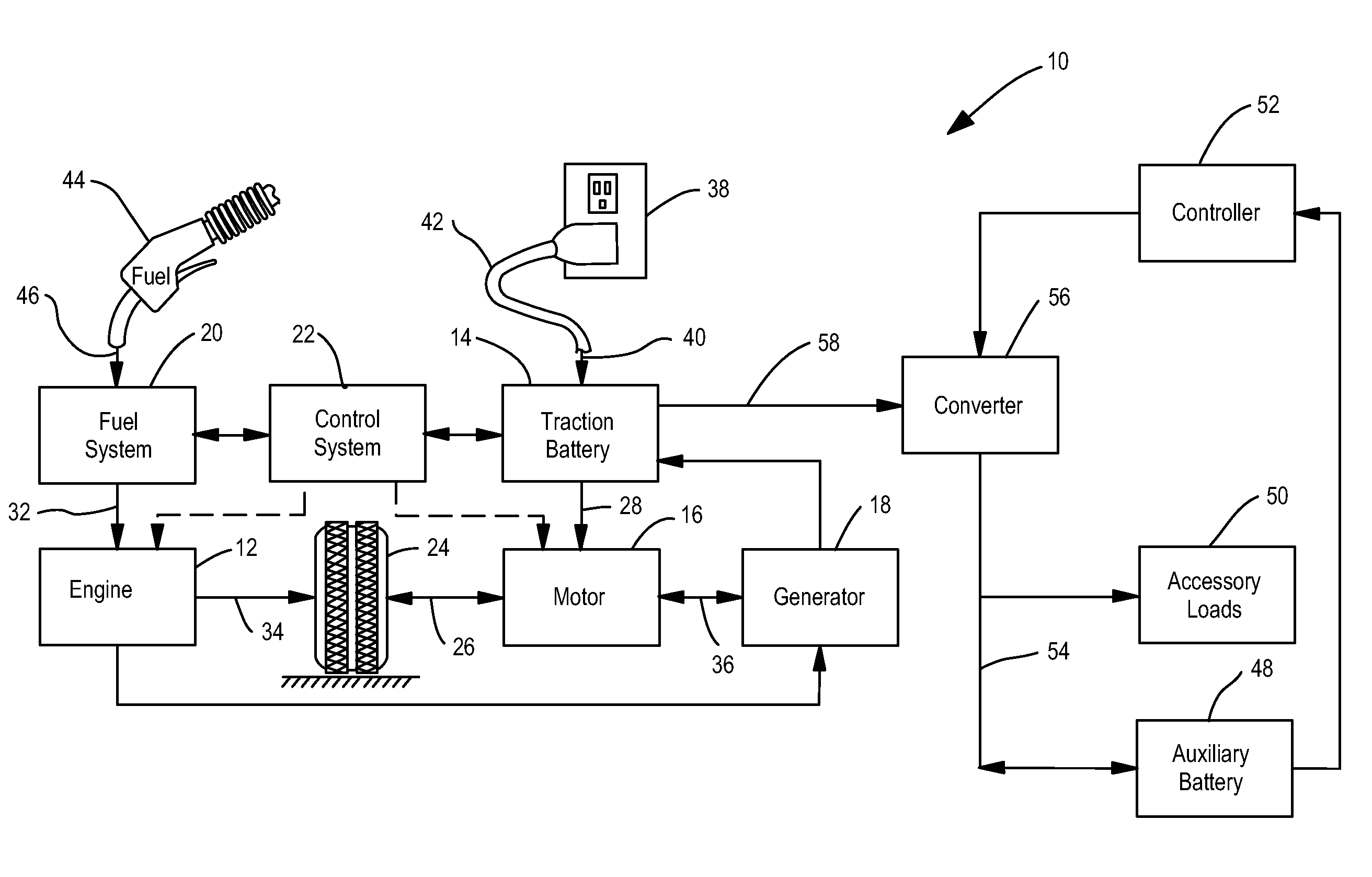
[0017]Referring now to FIG. 1, a block diagram of a plug-in hybrid electric vehicle (PHEV) in accordance with an embodiment of the present invention is shown. PHEV 10 includes an engine 12, a traction battery 14, an electric motor 16, a generator 18, a fuel sy...


PUM


Abstract

An electric vehicle includes a traction battery, an auxiliary battery, and a controller. The controller is configured to prevent the traction battery from charging the auxiliary battery while the auxiliary battery has more than a minimum energy. The controller is further configured to, upon the auxiliary battery having the minimum energy, enable the traction battery to charge the auxiliary battery such that the auxiliary battery is maintained at the minimum energy.

Description

BACKGROUND[0001]1. Technical Field[0002]The present invention relates to electric vehicles and a method of control.[0003]2. Background Art[0004]The term “electric vehicle” used herein encompasses battery electric vehicles (BEV), hybrid electric vehicles (HEV), and plug-in hybrid electric vehicles (PHEV).[0005]A BEV includes an electric motor, wherein the energy source for the motor is a traction battery. The BEV traction battery is re-chargeable from an external electric grid. The BEV traction battery is in effect the sole source of on-board energy for vehicle propulsion.[0006]A HEV includes an internal combustion engine and an electric motor, wherein the energy source for the engine is fuel and the energy source for the motor is a traction battery. The engine is the main source of energy for vehicle propulsion with the HEV traction battery providing supplemental energy for vehicle propulsion (the HEV traction battery buffers fuel energy and recovers kinematic energy in electric for...

Claims


Application Information

Patent Timeline
Patent Type & Authority Patents(United States)
IPC IPC(8): B60W10/00B60L1/00H02J7/00
CPCB60L7/18B60L11/14B60L11/1816B60L11/1861B60L11/1868B60L15/2045B60L11/123Y02T90/14B60L2210/20Y02T10/6217Y02T10/7005Y02T10/7044Y02T10/7066Y02T10/7077Y02T10/725Y02T10/7283Y02T90/127Y02T10/7072B60L53/14B60L50/61B60L50/16B60L58/12B60L58/20Y02T10/62Y02T10/70Y02T10/64Y02T10/72Y02T90/12
Inventor STANEK, JOSEPHOCHOCINSKI, CHRISTOPHER ADAM
Owner FORD GLOBAL TECH LLC
Learn More