Equipment for discharging a fixed amount of a particulate body

a technology of particulate body and equipment, which is applied in the direction of conveyor parts, loading/unloading, transportation and packaging, etc., can solve the problems of increasing equipment cost and maintenance expenses of rotating machines and electric motors, and large installment space, and achieves low equipment cost and maintenance expenses. , the effect of high quantitative precision

Active Publication Date: 2013-09-17
J POWER ENTECH
View PDF11 Cites 9 Cited by
  • Summary
  • Abstract
  • Description
  • Claims
  • Application Information

AI Technical Summary

Benefits of technology

[0010]The first aim of the present invention is to provide a discharging equipment for discharging fixed amounts of particulate bodies from a plurality of containers containing the particulate bodies, simultaneously and continuously. The second aim is to provide a discharging equipment in which the numbers of rotating machines and electric motors are small and the equipment cost and maintenance expense are low. The third aim is to provide a discharging equipment not requiring a large installment space in the vertical direction. The fourth aim is to provide a discharging equipment capable of carrying the discharged particulate bodies to a particular place. The fifth aim is to provide a discharging equipment capable of discharging particulate bodies at a high quantitative precision.Techinical Solution
[0019]The discharging equipment of the present invention can discharge fixed amounts of particulate bodies from a plurality of containers containing the particulate bodies, simultaneously and continuously. This discharging equipment uses small numbers of rotating machines and electric motors and accordingly requires small amounts of equipment costs and maintenance expenses. The discharging equipment requires no large installment space in the vertical direction. Further, the discharging equipment can carry the particulate bodies discharged, together to a particular place. The discharging equipment can discharge particulate bodies at a high quantitative precision.

Problems solved by technology

. . 90e and the belt conveyor 122, the numbers of the rotating machines and electric motors for driving them become inevitably large, increasing the equipment cost and the expenses for maintenance of the rotating machines and electric motors.
Consequently, a large installment space is required in a vertical direction, posing a problem.

Method used


Image

  • Equipment for discharging a fixed amount of a particulate body
  • Equipment for discharging a fixed amount of a particulate body
  • Equipment for discharging a fixed amount of a particulate body

Examples


Embodiment Construction

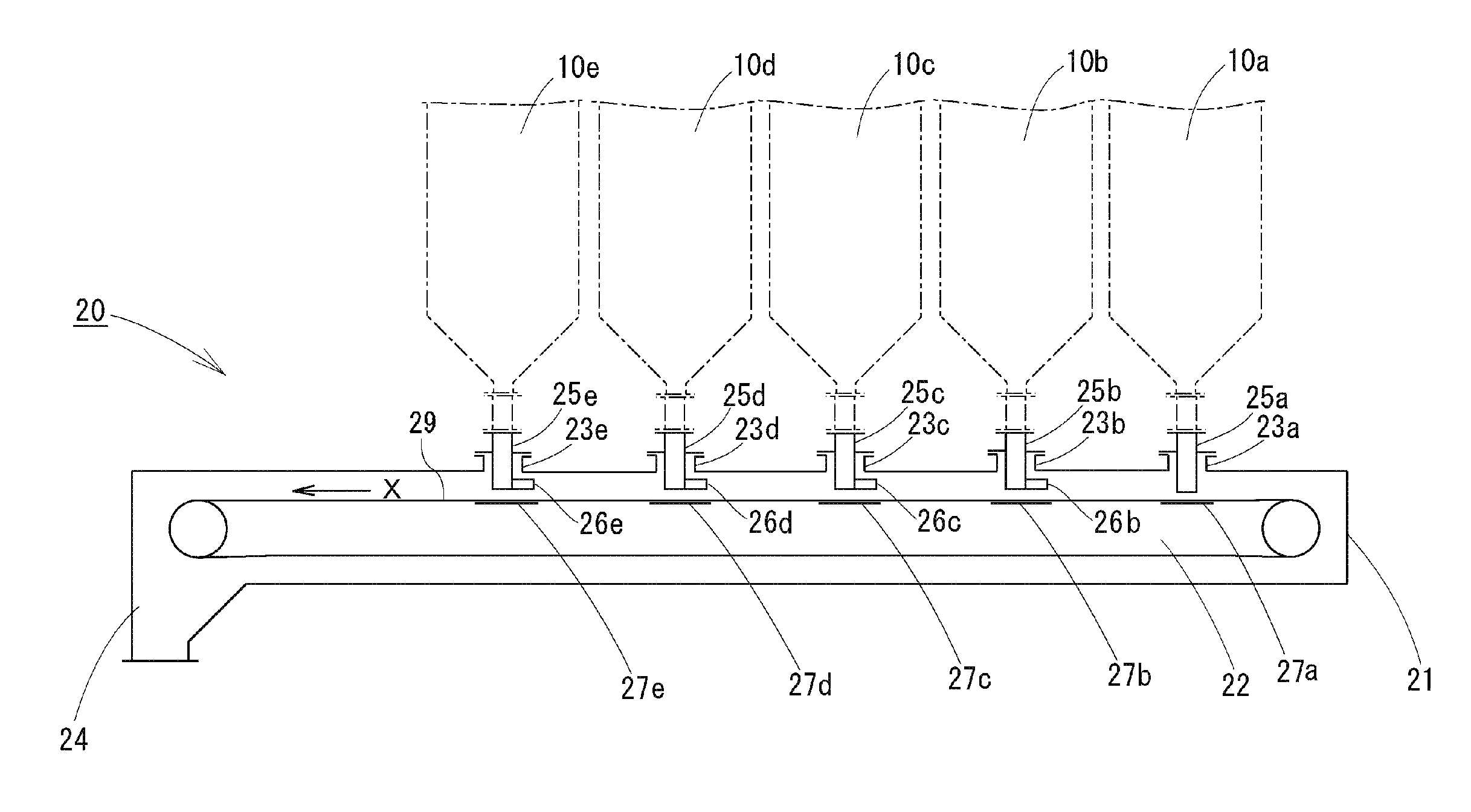
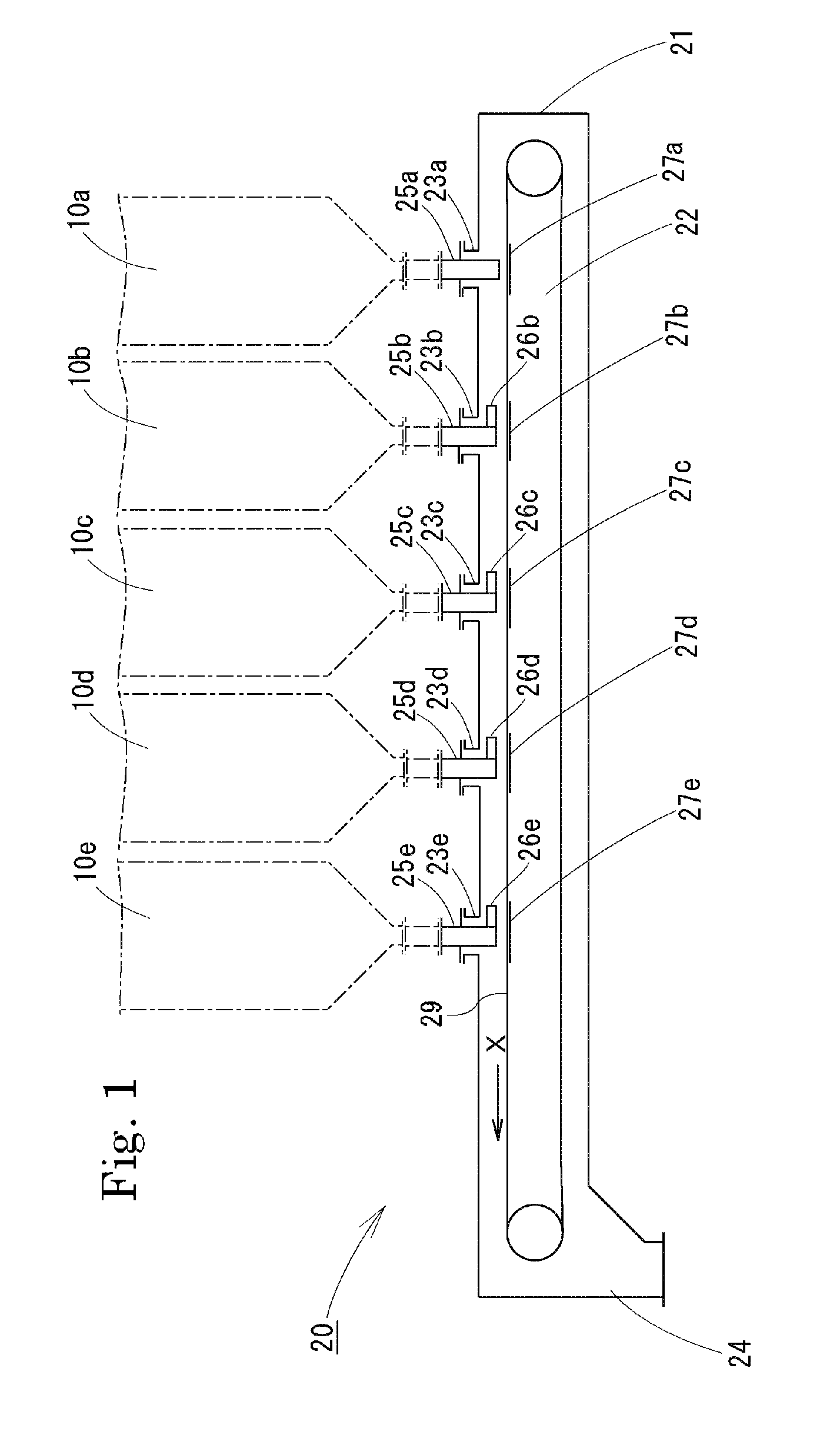
[0037]An embodiment of the present invention is explained below referring to the accompanying drawings. As shown in FIG. 1, the discharging equipment 20 of the present invention is a discharging equipment which discharges particulate bodies simultaneously from a plurality (5 in FIG. 1) of containers 10a, 10b, . . . 10e each containing the particulate body. In the present invention, the container includes not only a container storing a particulate body but also apparatuses through which a particulate body passes in a predetermined residence time for continuous treatment. As such a container, there are a reactor, heat exchanger, etc. used in industrial processes.

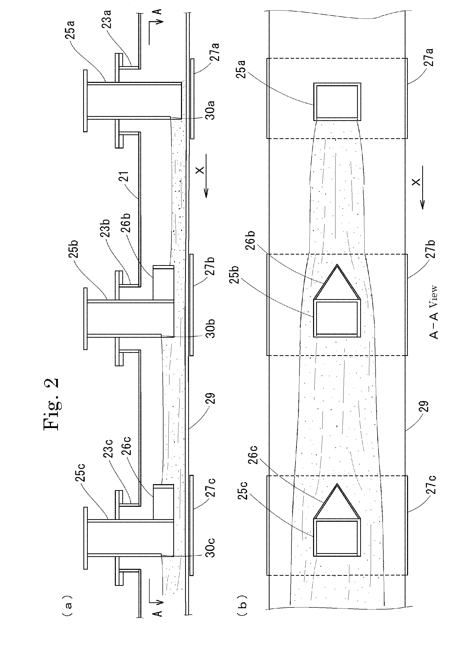
[0038]The discharging equipment 20 comprises a casing 21 equipped with a plurality of particulate body inlets 23a, 23b, . . . 23e and a single particulate body outlet; a belt conveyor 22 provided inside the casing 21; and supply pipes 25a, 25b, . . . 25e fitted to the particulate body inlets 23a, 23b, . . . 23e.

[0039]The casi...


PUM


Abstract

Fixed amount discharging equipment for simultaneously discharging a particulate body from a plurality of containers containing the particulate body, comprising a casing to the interior of which is provided a belt conveyor and having a particulate body discharge hole below the carrying direction end of the belt conveyor, and a plurality of supply arranged in the carrying direction of the belt conveyor and passing through the casing, lower ends thereof penetrating into the casing and being arranged above the belt of the belt conveyor, the lower ends of the supply pipes being such that the downstream sides thereof in the belt carrying direction have notches of a predetermined length from the end faces upward.

Description

[0001]This application is a 371 application of PCT / JP2009 / 053548 filed Feb. 26, 2009.TECHNICAL FIELD[0002]The present invention relates to a discharging equipment for discharging, from a plurality of containers containing a particulate body, the particulate body simultaneously and continuously.BACKGROUND ART[0003]As the discharging machine for continuously discharging a fixed amount of a particulate body from a container containing the particulate body, there are in use a belt feeder, a vibration feeder, a screw feeder, a rotary feeder, a roll feeder, etc. of these, a belt feeder and a roll feeder are often used when it is necessary to set a precise flow rate.[0004]In the industry handling a particulate body, there is often needed an equipment for discharging a particulate body simultaneously from a plurality of containers each containing the particulate body and carrying the particulate body into a container. In such a case, one discharging machine such as mentioned above is provid...

Claims


Application Information

Patent Timeline
Patent Type & Authority Patents(United States)
IPC IPC(8): B65G47/19
CPCB65G65/42B65G47/19
Inventor FURUYAMA, KUNINORIMIYA, MASAHIROSUZUKI, RYO
Owner J POWER ENTECH
Why Eureka
Try Eureka