Sheet processing apparatus and image forming apparatus

a technology of image forming apparatus and processing apparatus, which is applied in the field of sheet processing apparatus, can solve the problems of unnecessary deflection formed at the middle part of the sheet, and achieve the effect of improving the folding accuracy of the sh

Inactive Publication Date: 2013-09-17
RICOH KK
View PDF20 Cites 4 Cited by
  • Summary
  • Abstract
  • Description
  • Claims
  • Application Information

AI Technical Summary

Benefits of technology

[0009]The present invention has been made in light of the above points and may provide a sheet processing apparatus to improve the folding accuracy of a sheet and an image forming apparatus.
[0012]According to embodiments of the present invention, the folding accuracy of a sheet can be improved.

Problems solved by technology

However, if the distance between the conveyance guide plates is large as described above, an unnecessary deflection is formed at the middle part of the sheet.

Method used


Image

  • Sheet processing apparatus and image forming apparatus
  • Sheet processing apparatus and image forming apparatus
  • Sheet processing apparatus and image forming apparatus

Examples


first embodiment

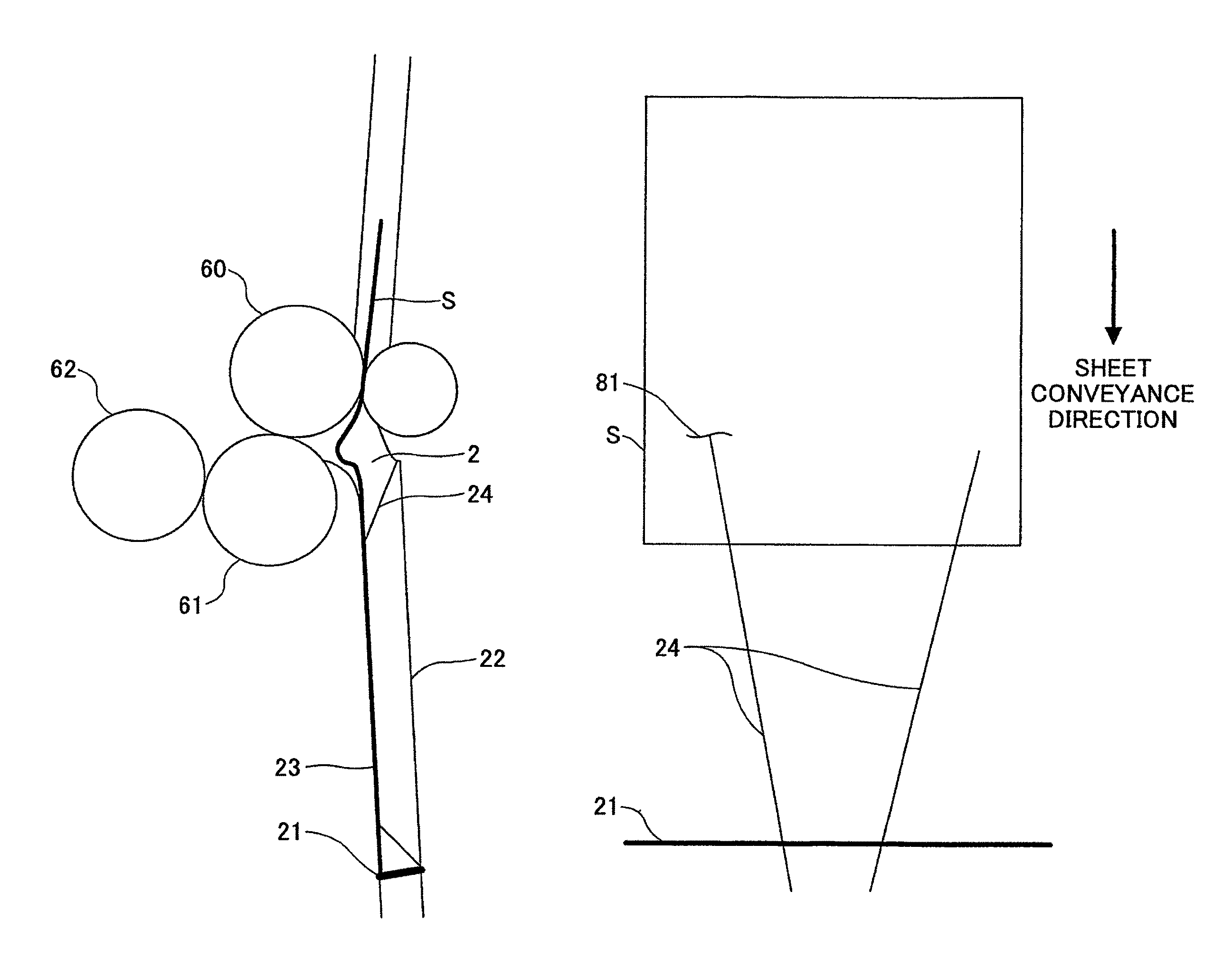
[0088]Next, a deflection controlling unit according to the embodiments is described. FIG. 13 is a diagram showing the conveyance path, which is provided between the stopper serving as the contact unit with which the tip end or the rear end of the conveyed sheet comes into contact and the folding rollers serving as the folding units.

[0089]As shown in FIG. 13, the conveyance path 2, which is provided between the stopper serving as the contact unit with which the tip end or the rear end of the conveyed sheet comes into contact and the folding rollers serving as the folding units, is configured to have a predetermined space with the stopper guide plates 22 and 23 serving as the conveyance guide plates.

[0090]At the sheet conveyance surface of the stopper guide plate 22 constituting the conveyance path, mylars 24 that are elastic substances having a smooth front surface and made of, for example, a plate-like member are attached as the deflection controlling units. For example, the mylars ...

second embodiment

[0127]Next, a second embodiment of the present invention is described. FIG. 20 is a diagram in which a driving mechanism is provided on one of the conveyance guide plates constituting the conveyance path. As shown in FIG. 20, the driving mechanism serving as a conveyance path space-controlling unit is connected to the stopper guide plate 22 constituting the conveyance path 2. The driving mechanism is constructed by, for example, an arm 26, an arm 27, and a cam 28. The cam 28 is connected to a motor, not shown. Further, the stopper guide plate 23 is attached to a sheet surface sensor 29. Note that the conveyance paths 3, 4, and the like can have the same configuration as the conveyance path 2.

[0128]The stopper guide plate 22 is capable of moving in the directions as indicated by an arrow C with the driving mechanism described above. When the stopper guide plate 22 moves to the stopper guide plate 23, a distance between the stopper guide plates 22 and 23 can be made smaller.

[0129]The ...


PUM

PropertyMeasurementUnit
degree of freedomaaaaaaaaaa
conductiveaaaaaaaaaa

Abstract

Disclosed is a sheet processing apparatus that forms folding lines at a predetermined position of a sheet after image formation and outputs the sheet. The apparatus includes a contact unit with which a tip end or a rear end of the conveyed sheet comes into contact and by which a deflection is formed at a middle part of the sheet; folding units that form the folding lines by conveying the middle part of the sheet, at which the deflection is formed by the contact unit, between the folding units; and a deflection controlling unit that controls the deflection at the middle part of the sheet formed by the contact unit.

Description

BACKGROUND OF THE INVENTION[0001]1. Field of the Invention[0002]The present invention relates to a sheet processing apparatus that performs a folding operation such as a Z-shape folding operation on a sheet ejected from an image forming apparatus like a printing apparatus. In addition, the present invention relates to the image forming apparatus equipped with the sheet processing apparatus.[0003]2. Description of the Related Art[0004]Up until now, a known sheet processing apparatus is included in an image forming apparatus such as a copier and a printer and performs a folding operation such as a Z-shape folding operation on a sheet on which an image has been formed by an image forming unit and the like. In such a sheet processing apparatus, a member with which the tip end or the rear end of a sheet comes into contact is provided, for example, on a conveyance path for conveying the sheet on which an image has been formed. When the sheet comes into contact with the member, a deflectio...

Claims


Application Information

Patent Timeline
Patent Type & Authority Patents(United States)
IPC IPC(8): B31F1/00
CPCB31F1/00B65H45/142B65H2801/27
Inventor HONDA, MASAO
Owner RICOH KK
Why Eureka
Try Eureka