
Method and apparatus for making a light weight container

a container and light weight technology, applied in the direction of rigid containers, transportation and packaging, other domestic articles, etc., can solve the problems of weakening of containers, unacceptably thin walls near the top and bottom of containers, and existing containers, etc., to achieve more even distribution of thermoplastic materials

Active Publication Date: 2013-09-17
MID AMERICA MACHINING
View PDF28 Cites 17 Cited by
  • Summary
  • Abstract
  • Description
  • Claims
  • Application Information

AI Technical Summary

Benefits of technology

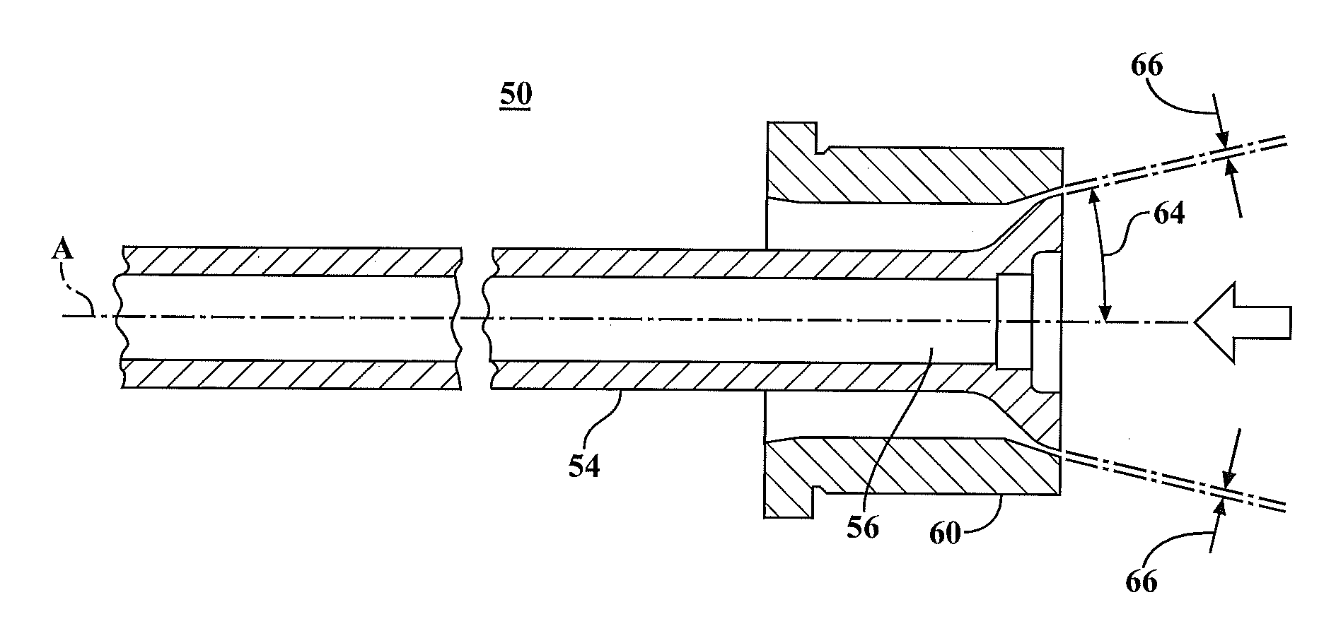
[0008]In summary, a thin-walled container in accordance with the present invention is formed having sidewalls, a bottom, a top having a neck, a handle, and a spout. The container has eight sides, and a smoothly tapered radius between the spout and the sidewall. To form the container, specialized round tooling is utilized in the die and its associated mandrel to achieve more even distribution of the thermoplastic material during the molding process. The resulting container displays a more efficient distribution of the materials along the sidewalls, top and bottom of the container, typically at a weight of fifty-two grams or less.
[0009]It is an object of the present invention, therefore, to provide a thin-walled container having an extremely light weight. Further, it is an object of the present invention to provide a thin-walled container having six or more sides and a specially radiused transition between the spout and sidewall of the container.
[0010]It is another object of the present invention to position the handle of the container to improve venting of the interior of the container during the pouring process.

Problems solved by technology

These multiple spaced apart transitions often result in excessively thin walls at the transitions, thereby weakening the container.
The existing containers, however, suffer from important limitations.
Particularly, as known in the prior art, the manufacture of thin-walled thermoplastic containers utilizing the blow-molding techniques can create unacceptably thin wall dimensions near the top and bottom of the containers, where the tops and bottoms of the containers join the side walls.
Excessive thinning in these areas weakens the overall container and reduces its ability to withstand the forces typically imposed during the filling process.

Method used


Image

  • Method and apparatus for making a light weight container
  • Method and apparatus for making a light weight container
  • Method and apparatus for making a light weight container

Examples


first embodiment

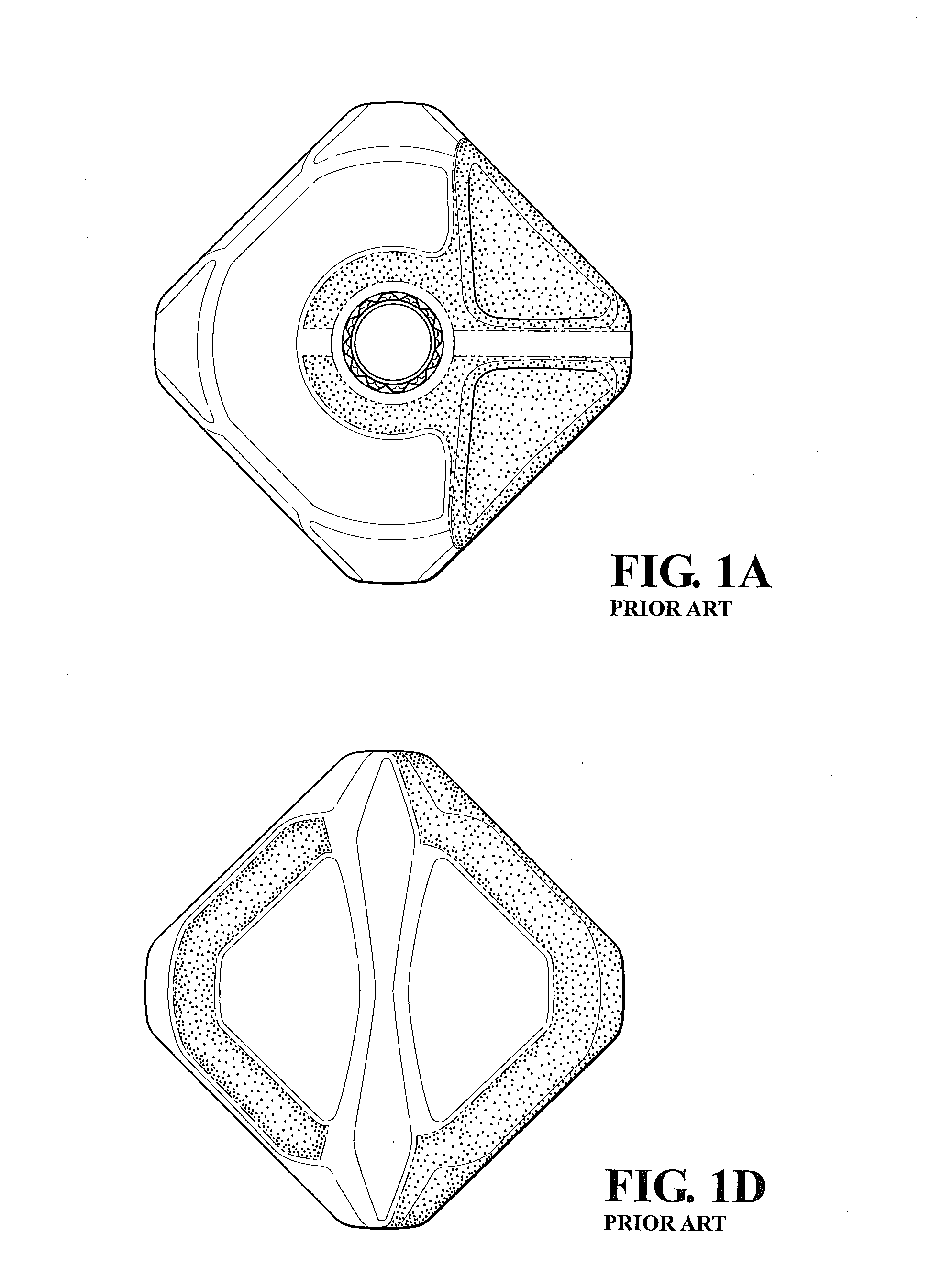
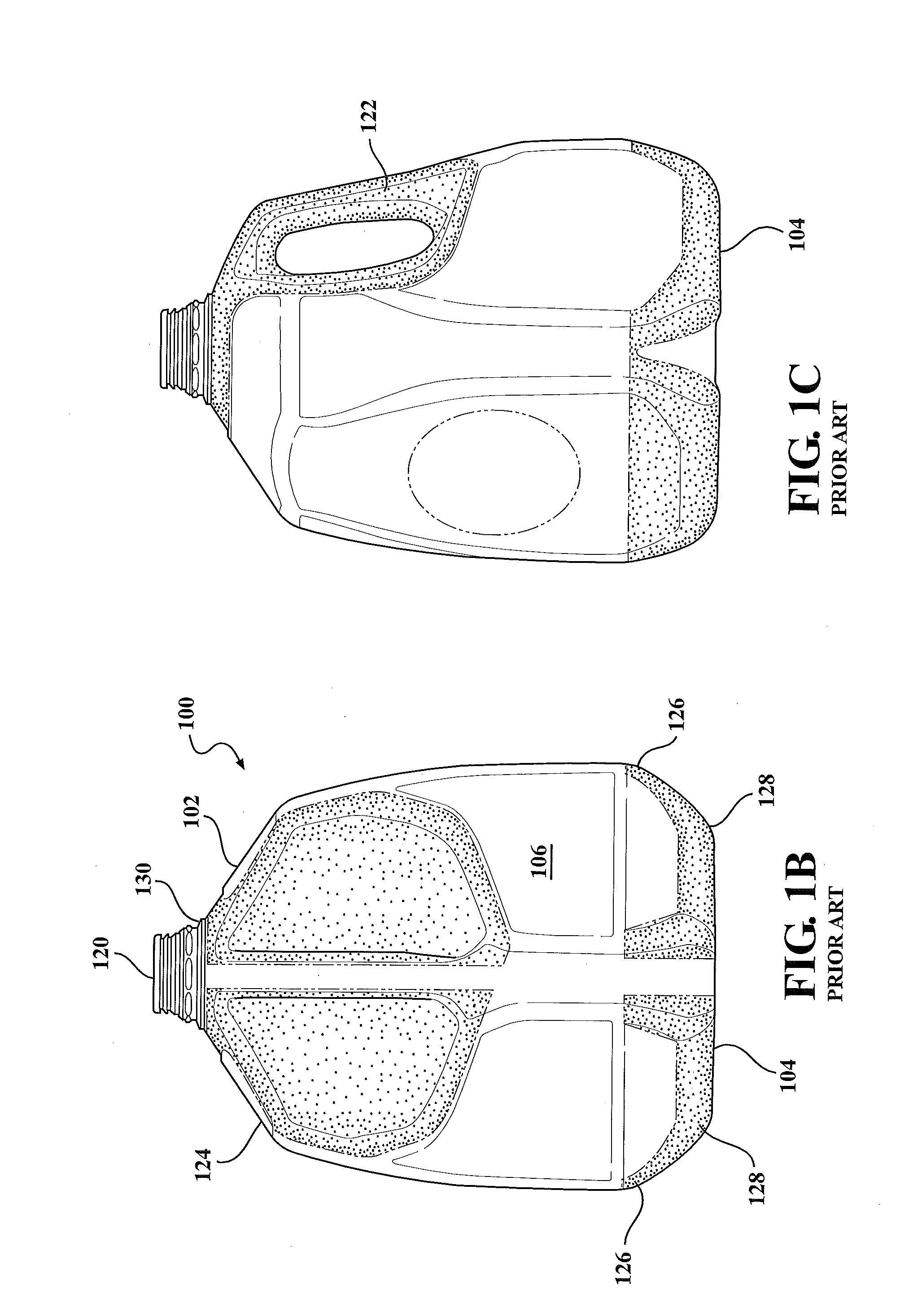
[0035]Turning now to FIGS. 2A-2E, a container formed according to the present invention is disclosed. Container 10 consists of a top section 12, a bottom 14 and a plurality of sidewalls. Eight sidewalls alternate in dimension, four being long sidewalls 16 and four being short sidewalls 18. The top section 12 is configured with a spout 20 having an opening 21 by which material may be introduced into the interior of the container 10. The container is molded as a single piece, and includes a handle 22 which is hollow and permits liquid and air to pass inside it. Preferably, the handle is configured adjacent to a short sidewall 18, so that when the container is held for pouring, the center of mass is concentrated along the axis which intersects both the handle and the opposing short sidewall of the container.

[0036]In a first embodiment, the height of the container 10 is measured from the bottom of the container to the bottom of the spout is approximately 9.231 inches, for a container ha...

second embodiment

[0037]the invention as disclosed in FIGS. 3A and 3B, which does not include the ribs 30 but does include the same upper radius transition 24. Containers of either configuration may be formed with one or more volume control inserts 32 molded into one or more sides of the container to adjust the total internal volume of the container 10.

[0038]Turning now to first embodiment of the invention as shown in FIGS. 2A-E, it will be appreciated that the top section 12 of the container 10 incorporates an upper radius transition of radius R between the bottom of the spout 20 and the top of sidewalls 16 and 18. The absence of the sharp transitions between the bottom of the spout and the container top, and the top of the sidewall in the container top results in increased strength while allowing for even distribution of the thermoplastic material, eliminating the sharp transitions of the prior art. The inclusion of rib 28 imparts additional strength to this vital section of the container.

[0039]Lik...


PUM

PropertyMeasurementUnit
heightaaaaaaaaaa
heightaaaaaaaaaa
weightaaaaaaaaaa

Abstract

An improved lightweight container incorporates a thinner wall structure in an essentially octagonal container having a bottom member, a plurality of sidewalls, a spout, an upwardly converging neck member coupling the sidewalls of the spout, a handle molded into the container and a radiused transiting section between the sidewalls and the spout which eliminates weakened corner sections and improves overall strength to weight ratios.

Description

RELATED U.S. APPLICATION[0001]This application is a continuation of U.S. patent application Ser. No. 13 / 405,495 filed Feb. 27, 2012, which claims the benefit of U.S. Provisional Application No. 61 / 466,588 filed Mar. 23, 2011.FIELD OF THE INVENTION[0002]The present invention relates to containers for storage of liquids, granular materials and the like, and methods and apparatuses for forming the same. More particularly, the container of the present invention is a single piece blow-molded plastic container formed in a multi-sided configuration with modified corner radii, utilizing a smaller volume of raw material to obtain volumes and strength equivalent to the prior art.DESCRIPTION OF THE RELATED ART[0003]Blow-molded plastic bottles are well known for use for holding a wide variety of liquids such as milk, water and juice. The same types of containers may be used for granular materials. Containers of this type are manufactured in a variety of sizes, conventionally formed of a variety...

Claims


Application Information

Patent Timeline
Patent Type & Authority Patents(United States)
IPC IPC(8): B29C49/04
CPCB29C49/04B65D23/10B29D22/003B65D1/0223B65D1/02B29C49/48B29C49/4802B65D2501/0081B29C2049/4892B29C2049/4882B29K2105/256B29L2031/712B29C49/482B29C2049/4879B29C2049/4889
Inventor LOBBESTAEL, PETERVANOVER, ALGAYDOSH, KEVIN DHALL, GREGORY T
Owner MID AMERICA MACHINING
Learn More