
Image photographing apparatus, method of controlling image photographing apparatus and control program

a technology of image photographing and control program, which is applied in the direction of instruments, television systems, static indicating devices, etc., can solve the problems of increasing power consumption, affecting the effect of image display, and consuming a lot of battery power, so as to reduce the power for displaying a photographed image, without involving higher costs or increasing siz

Active Publication Date: 2013-09-17
SNAPTRACK
View PDF18 Cites 2 Cited by
  • Summary
  • Abstract
  • Description
  • Claims
  • Application Information

AI Technical Summary

Benefits of technology

[0010]The present invention provides an image photographing apparatus, a method of controlling the image photographing apparatus, and a control program which are capable of suppressing power consumption when in photographing mode, capable of allowing a photographer to perform photographing while confirms an entity of the real world directly without involving higher costs or increased size, and capable of allowing the photographer to positively determine the photographing field angle without any erroneous operations.
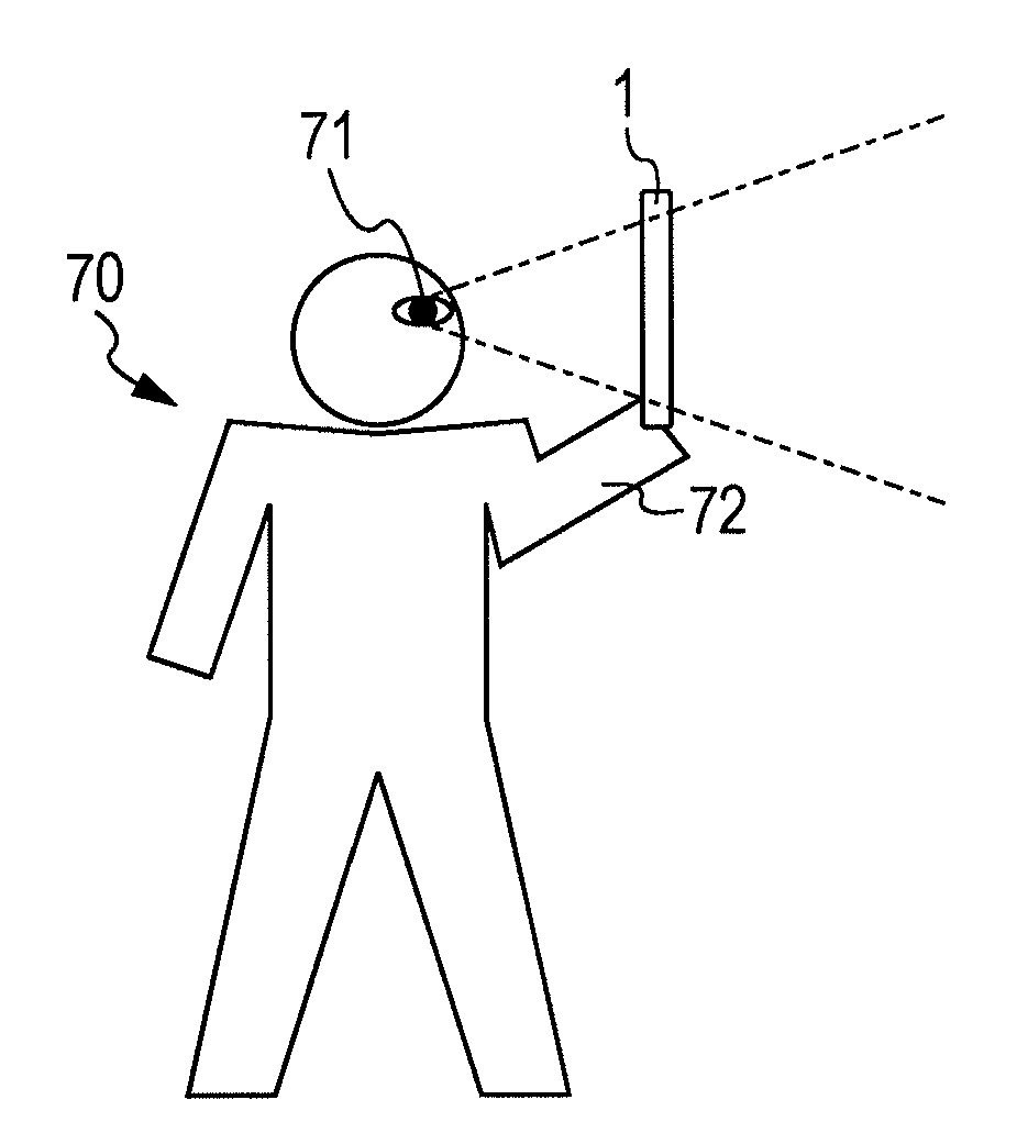
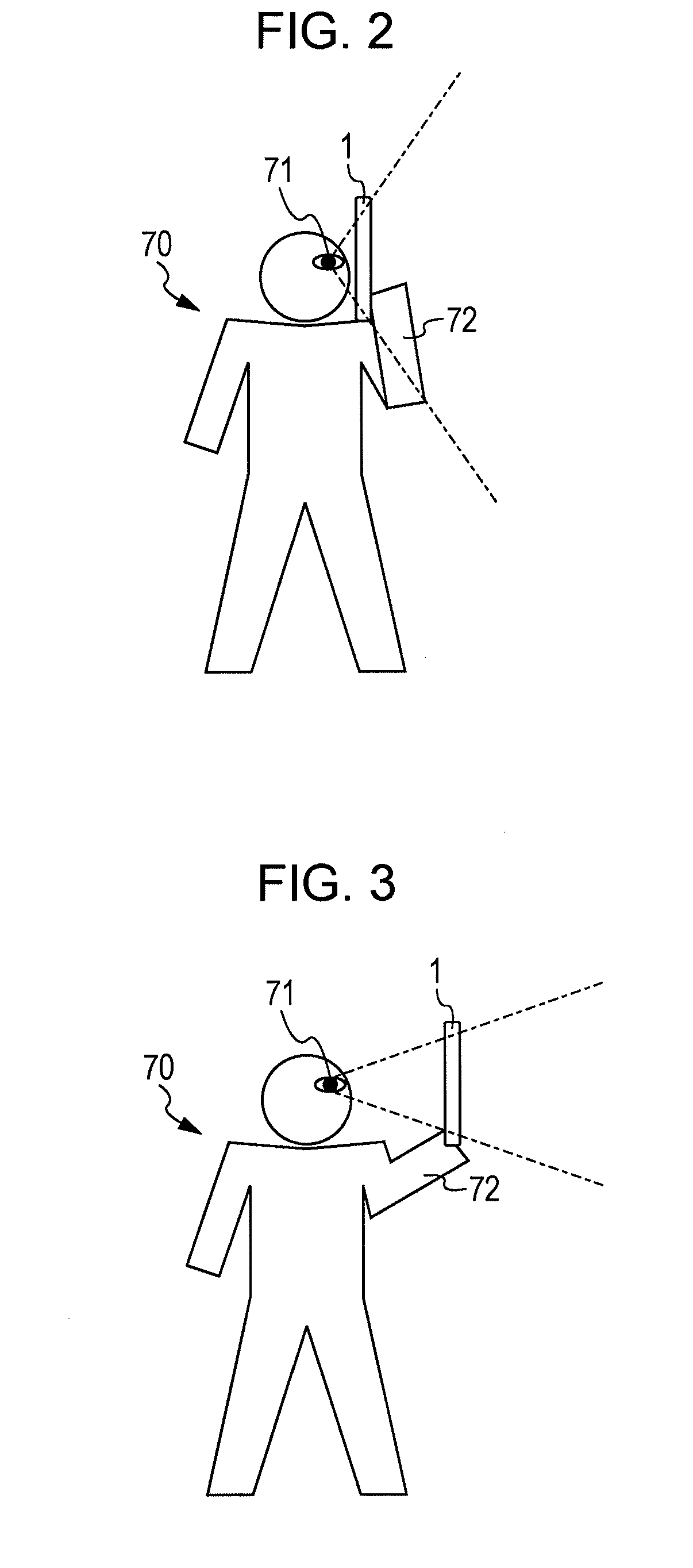
[0012]That is, according to the present invention, when in photographing mode, the display surface of the transmissive display section is set to be in a transmissively viewable state and is used as an optical finder to thereby reduce power for displaying a photographed image on the transmissive display section. Further, when in photographing mode, the photographing field angle using a zoom function of the camera section is determined in response to the distance which the distance detection section detects. In other words, the photographing field angle using the zoom function of the camera section is determined so as to fit a viewing angle (finder field angle) as viewed through the display surface of the transmissive display section by the photographer. Herewith, it is possible to fit the viewing angle (finder field angle) and the photographing field angle.
[0013]In the present invention, when in photographing mode, the display surface of the transmissive display section is set to be in a transmissively viewable state and is used as an optical finder, so that power consumption when in photographing mode is suppressed, and the photographer can perform photographing while confirming an entity of the real world directly without involving higher costs or increased size. Further, in the present invention, since the photographing field angle using the zoom function of the camera section is determined in response to the distance which the distance detection section detects, the photographer is able to positively determine the photographing field angle without any erroneous operation by an intuitive operation for changing the distance from the point of view of the photographer to the display surface of the display section.

Problems solved by technology

Therefore, in the digital camera and the cellular phone terminal, power consumption increases even in the draft state, so that the battery may be exhausted.
In addition, in the digital camera and the cellular phone terminal according to the related art, it takes a time to some degree from capturing by the image capturing device to updating the image data in the memory for the display device.
In particular, when the photographing is performed under a low luminance environment, an exposure time of the photographing device is elongated and the output frame rate is slower.
Therefore, the display image on the display device looks likes a moving image in which so-called frame omission occurs, and the movement of the subject image is often awkward and feels uncomfortable.
In general, since the photographer determines timing for releasing the shutter while looking at the image on the display device, when the frame omission occurs in the display image as described above, it is difficult to release the shutter at a proper timing.
As a result, a chance for a picture may be missed.
Further, the above problem hardly occurs in the film camera according to the related art in which the real-world entity can be directly confirmed via an optical finder, but becomes a special problem in the recent camera function of the digital camera or the cellular phone terminal.
However, in a case of the cellular phone terminal which is limited in housing volume capacity, it is not preferable to also provide the device such as the optical finder.
However, when the highly-sensitive photographing device or the camera optical system with high light-gathering capability is provided, the cost is increased and the size is increased, which is not preferable.
However, when the high-performance CPU or the memory corresponding to the high-speed read / write operation is mounted, the cost is increased and the power consumption is also increased.
However, mounting locations of these buttons or the switches, operations of these buttons, the operation of the camera, and direction assignment of the zoom-up / zoom-down are different according to the types of cameras, so that it is difficult for these assignments to be distinguished to the photographer.

Method used


Image

  • Image photographing apparatus, method of controlling image photographing apparatus and control program
  • Image photographing apparatus, method of controlling image photographing apparatus and control program
  • Image photographing apparatus, method of controlling image photographing apparatus and control program

Examples


Embodiment Construction

[0028]Hereinafter, reference is made to the drawings to describe an embodiment of the present invention.

[0029]An example to which the present invention is applied includes a camera-equipped cellular phone terminal in the present embodiment. Of course, the content to be described here is only an example, and it goes without saying that the invention is not limited to this example.

Schematic Appearance Configuration of Cellular Phone Terminal

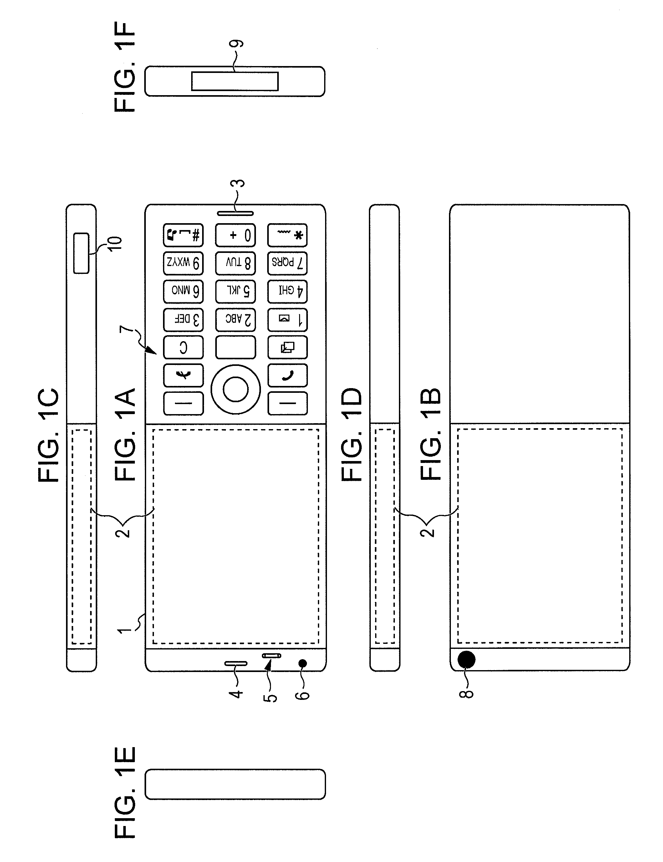
[0030]FIG. 1 shows a schematic appearance configuration example of a cellular phone terminal 1 according to this embodiment. FIG. 1A shows a schematic front view of the cellular phone terminal 1 according to the embodiment, FIG. 1B shows a schematic side view, and FIGS. 1C to 1F show schematic side views with respect to the front view of FIG. 1A, respectively. Meanwhile, each of the devices to which referential marks are attached in FIG. 1 is a portion of all devices that the cellular phone terminal 1 includes. The cellular phone terminal 1 accordi...


PUM


Abstract

An image photographing apparatus is provided, which includes a camera section having a zoom function for changing a photographing field angle, a transmissive display section including a display surface that allows sides facing each other to be transmissively viewed from both directions of a housing front side and a housing back side, a distance detection section that detects a distance from a point of view of a photographer to the display surface of the display section, and a control section. The control section controls the display surface of the transmissive display section in a transmissively viewable state when in photographing mode so as to perform photographing by the camera section, and determines a photographing field angle using the zoom function of the camera section in response to the distance detected by the distance detection section.

Description

BACKGROUND OF THE INVENTION[0001]1. Field of the Invention[0002]The present invention relates to an image photographing apparatus including an image capturing device and a display device, a method of controlling the image photographing apparatus, and a control program.[0003]2. Description of the Related Art[0004]In Japanese Unexamined Patent Application Publication No. 2006-121344 (FIG. 1), there is disclosed a digital single-lens reflex camera which retreats a movable mirror from a photographing light-path, continuously captures subject images in a state where a focal plane shutter is opened, and displays the image on a monitor screen. In addition, in the digital single-lens camera described in Japanese Unexamined Patent Application Publication No. 2006-121344 (FIG. 1), when a photographer does not look into a finder eyepiece and manually operates a focus regulating operation member, the electronic viewfinder function is operated. Therefore, according to the digital single-lens ref...

Claims


Application Information

Patent Timeline
Patent Type & Authority Patents(United States)
IPC IPC(8): H04N7/18
CPCG03B15/00G09G3/001G09G2340/04G09G2340/14G09G2354/00
Inventor FURUTANI, MASAHIROYAMAMOTO, TAKASHIOHMORI, KENJI
Owner SNAPTRACK
Learn More