Fluid dispensing apparatus

a technology of liquid dispensing and liquid cylinder, which is applied in the direction of rigid containers, portable flexible containers, containers, etc., can solve the problems of reducing the note carrying capacity of atm cassettes, not always being able to mount the dispensing mechanism in the lid, and being vulnerable to theft. , to achieve the effect of low cos

Inactive Publication Date: 2013-09-24
SPINNAKER INT
View PDF8 Cites 38 Cited by
  • Summary
  • Abstract
  • Description
  • Claims
  • Application Information

AI Technical Summary

Benefits of technology

[0009]The fluid dispensing apparatus of the present invention provides a compact, lightweight and low cost solution to the problem of mounting a spoiling or degradation agent dispensing system in the base of an ATM cassette or the like.

Problems solved by technology

ATM cassettes are an attractive target for thieves, since they may contain 2000 bank notes or more, and are particularly vulnerable to theft during transportation and delivery to an ATM.
However, due to complex design and variations between models of ATM cassette it is not always possible to mount the dispensing mechanism in the lid.
However, this can reduce the note carrying capacity of the ATM cassette, thereby increasing the frequency with which the cassette has to be replaced or replenished.
This is undesirable, as ATM operators typically have to pay a fee to a licensed security company for replenishing the ATM, and thus reducing the frequency of replenishment of the ATM reduces cost for the ATM operator.
A problem with this type of system is that in order to obtain a satisfactory seal between the piston and the bore to ensure that there can be no leakage of the spoiling or degradation agent, the bore must be machined from a metal such as aluminium.
Given that a cash in transit company will typically handle a large number of ATM cassettes at one time any excess weight is highly undesirable.
Moreover, the cost of manufacturing a bore with sufficient precision to ensure a good quality seal between the bore and the piston and to prevent skewing of the piston in travel is prohibitive.

Method used


Image

  • Fluid dispensing apparatus
  • Fluid dispensing apparatus
  • Fluid dispensing apparatus

Examples


Embodiment Construction

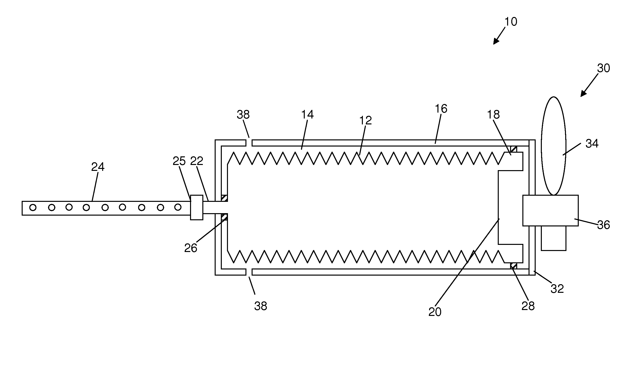
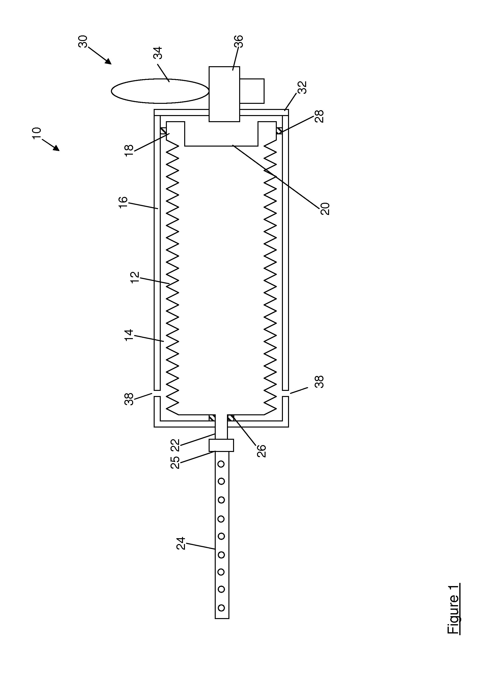
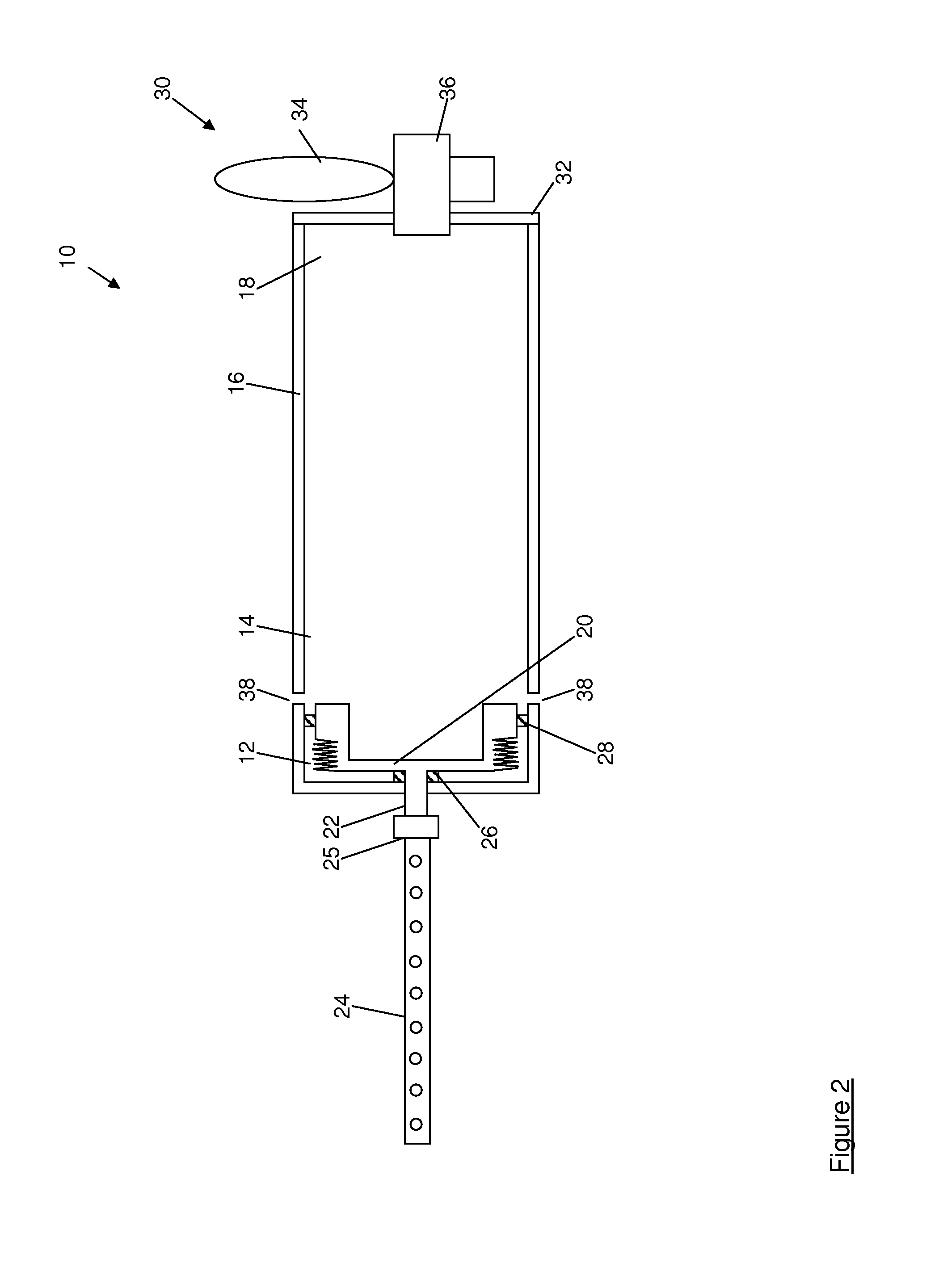
[0027]Referring first to FIG. 1, a fluid dispensing apparatus is shown generally at 10, and includes a collapsible bellows 12 containing a fluid spoiling or degrading agent such as indelible ink, adhesive or the like. The bellows 12 is housed in a bore 14 of a housing 16 of a lightweight plastics material. The housing 16 may be formed, for example, by extrusion of a plastics material, whilst the bellows 12 may be formed by blow-moulding a plastics material.

[0028]In this example the bellows 12 is generally cylindrical, and the housing 16 has a generally cylindrical bore 14 of a slightly larger diameter than that of the bellows 12, but it is to be appreciated that the bellows 12 may take any form.

[0029]One function of the bore 14 of the housing 16 is to guide the bellows 12 during compression to ensure that the bellows 12 compresses in a direction generally along a longitudinal axis thereof, to prevent or at least impede skewing or undesired lateral deformation of the bellows 12 durin...


PUM


Abstract

A fluid dispensing apparatus (10) comprising a collapsible bellows (12) for storing the fluid to be dispensed, a housing (14) for receiving the collapsible bellows and means (30) for compressing the collapsible bellows on actuation of the fluid dispensing apparatus (10) so as to eject the fluid through an outlet (22) of the bellows (12), wherein the housing (14) is configured to guide the bellows (12) so as to impede lateral deformation of the bellows (12) during compression thereof.

Description

CROSS-REFERENCES TO RELATED APPLICATION[0001]The present application claims priority to PCT / GB2011 / 050349, filed Feb. 23, 2011, which claims priority to Great Britain Patent Application No. 1003869.3, filed Mar. 9, 2009 entitled “A FLUID DISPENSING APPARATUS” incorporated by reference for all purposes.TECHNICAL FIELD[0002]The present invention relates to a fluid dispensing apparatus. In particular, the present invention relates to a fluid dispensing apparatus which is suitable for use in a container such as an ATM cassette.BACKGROUND TO THE INVENTION[0003]In order to facilitate the process of replenishing automated teller machines (ATMs) it is common for cassettes to be used to store bank notes, both in the ATM and in transit to and from ATMs. An empty ATM cassette can simply be removed from the ATM and replaced with a cassette which has been pre-filled with bank notes.[0004]ATM cassettes are an attractive target for thieves, since they may contain 2000 bank notes or more, and are p...

Claims


Application Information

Patent Timeline
Patent Type & Authority Patents(United States)
IPC IPC(8): E05G1/00
CPCE05G1/14G08B15/02G07F19/201
Inventor TRIPP, NICHOLASHAMMOND, PHILIPWASTELL, MARTIN
Owner SPINNAKER INT
Why Eureka
Try Eureka