Stopper, paper feeding device and multi-function printer

a paper feeding device and multi-function printer technology, applied in the direction of electrical equipment, thin material processing, article separation, etc., can solve the problems of invalidation of the functions of the first stopper and the second stopper, and consume a lot of space, so as to reduce the manufacturing reduce the cost of the paper feeding device. , the effect of increasing the printing quality

Inactive Publication Date: 2013-09-24
CAL COMP ELECTRONICS +1
View PDF7 Cites 0 Cited by
  • Summary
  • Abstract
  • Description
  • Claims
  • Application Information

AI Technical Summary

Benefits of technology

[0012]The present invention provides a multi-function printer having a good printing quality.
[0023]In light of the above, the stopper of the present invention is different in structure than the conventional stopper, and thus less components can be used and the fabricating costs of the paper feeding device can further be reduced by using the stopper of the invention. Furthermore, by application of the paper feeding device having the stopper of the invention in the multi-function printers, the papers can be effectively stopped and the papers are not interfered during the paper feeding process, and thus the paper can be maintained as original and the printing quality can further be increased.

Problems solved by technology

It should be noted that when the above plurality of office automatic equipment is simultaneously disposed in the office, a lot of space is consumed.
However, after the user opens the outer case of the MFP and repairs the components within the MFP and closes the outer case, the first stopper 110 or the second stopper 120 may fail to return to their original positions, and it may lead to the invalid of the functions of the first stopper 110 or the second stopper 120.
Furthermore, in such configuration, two stoppers are needed and thus material costs may relatively be increased.

Method used


Image

  • Stopper, paper feeding device and multi-function printer
  • Stopper, paper feeding device and multi-function printer
  • Stopper, paper feeding device and multi-function printer

Examples


first embodiment

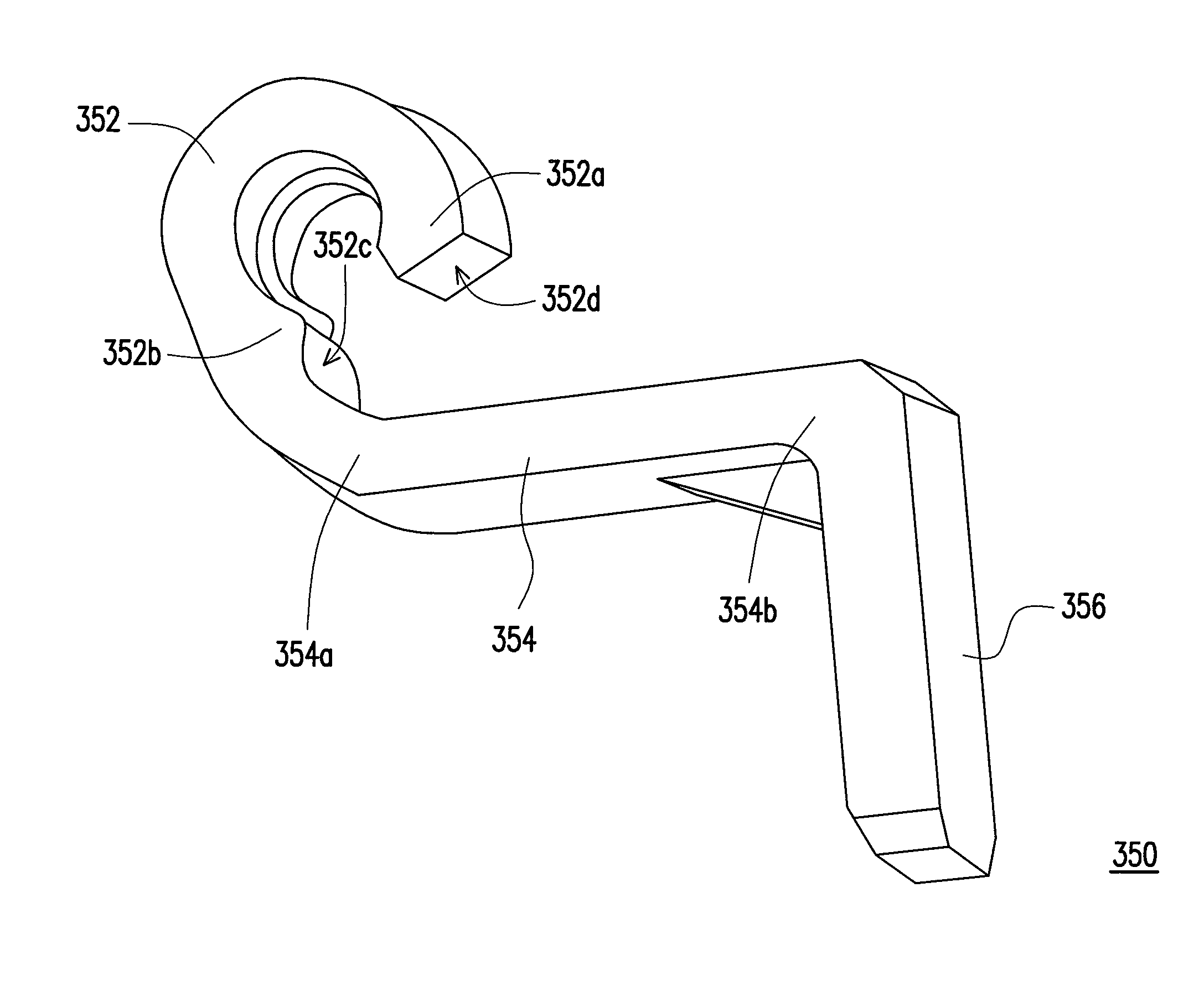
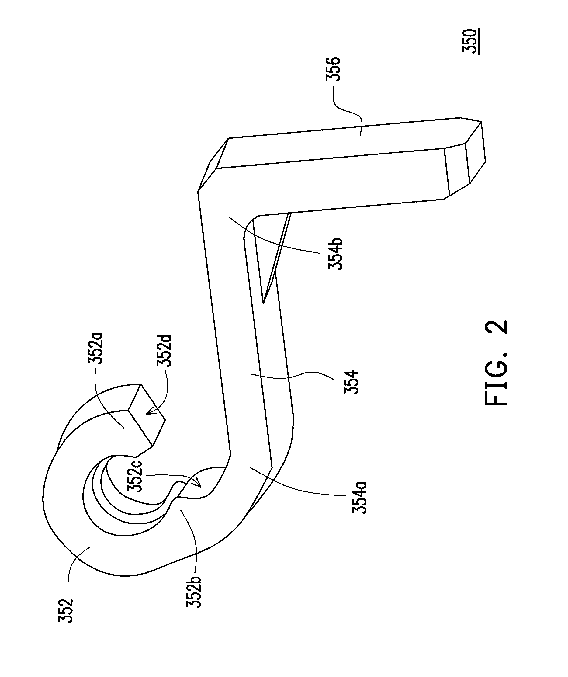
[0034]FIG. 2 is a schematic view of a stopper according to an embodiment of the present invention. FIG. 3 is a schematic view of a paper feeding device applying the stopper according to an embodiment of the present invention. Please refer to FIG. 2 and FIG. 3 together, the paper feeding device 300 includes an outer case 310 (shown in FIG. 5A), and inner case 320, a first axel 330, a first roller 340, a pair of stoppers 350, a second axel 360, a second roller 370 and a tray 380. The outer case 310 has a pair of side walls 312 and a pair of limiting protrusions 314, wherein each limiting protrusion 314 is correspondingly disposed at one of the side walls 312. The inner case 320 is located between the pair of side walls 312 of the outer case 310, and each side wall 312 is located between the inner case 320 and the corresponding limiting protrusion 314. The first axel 330 is pivoted to the inner case 320 and the side walls 312 and the two ends of the first axel 330 protrude to the outsi...

second embodiment

[0047]FIG. 6 is a schematic view of a stopper according to a second embodiment of the present invention. Please refer to FIG. 6, the difference between the present embodiment and the previous embodiment is that: the stopper 550 further has a limiting portion 558 connected to the first end 552a of the C-ring 552, and the limiting portion 558 extends along a radial direction of the C-ring 552.

[0048]FIG. 7A to FIG. 7C are schematic views showing the process flow of a multi-function printer having the stopper and performing paper feeding process according to an embodiment of the present invention. Please refer to FIG. 7A and FIG. 7B, when the multi-function printer 2000 performs printing or copying process, a side of the inner case 320 (as shown in FIG. 5A) pivoted with the first axel 330 moves along a clockwise direction toward the tray 380 by taking the second axel 360 as a rotating center, the first end 552a of each stopper 550 is propped against by the corresponding limiting protrus...


PUM


Abstract

A stopper, a paper feeding device including an inner and outer cases, a first and second axels, a first and second rollers, a pair of stoppers and a tray, and a multi-function printer are provided. The outer case has two side walls and two protrusions disposed on the side walls. The inner case is between the two side walls. The first axel pivots the inner case and the side walls. The first roller covers the first axel. The stoppers are disposed at outer side of the side walls, wherein each of the stoppers has a C-ring, a connecting portion and a stopping portion. Each C-ring pivoted to the first axel has a first and second ends, and the protrusions prop against to the first ends. The second axel pivots the inner case, and the second roller covers the second axel. The tray is disposed below the first roller.

Description

CROSS-REFERENCE TO RELATED APPLICATION[0001]This application claims the priority benefit of Taiwan application serial no. 100143346, filed on Nov. 25, 2011. The entirety of the above-mentioned patent application is hereby incorporated by reference herein and made a part of this specification.BACKGROUND OF THE INVENTION[0002]1. Field of the Invention[0003]The present invention is related to a stopper, a paper feeding device and a multi-function printer, and particularly to a stopper, a paper feeding device and a multi-function printer using the stopper, wherein the stopper has different structure than the conventional stopper.[0004]2. Description of Related Art[0005]As the information society arrives, office automatic equipments such as scanners, photocopiers or printers are disposed in offices, and users may perform secretarial processing operations using these office automatic equipments. It should be noted that when the above plurality of office automatic equipment is simultaneous...

Claims


Application Information

Patent Timeline
Patent Type & Authority Patents(United States)
IPC IPC(8): B65H3/52
CPCB65H3/0684B65H3/565H04N1/00588H04N1/00599H04N1/0062H04N1/00559B65H2403/513H04N2201/0094
Inventor HUANG, CHUNG-LIANG
Owner CAL COMP ELECTRONICS
Why Eureka
Try Eureka