Vacuum generation device for vacuum treatment of wounds

a vacuum generation and wound technology, applied in the field of portable devices, can solve the problems of user worry and the need for user control actions, and achieve the effects of reducing maloperations, improving overall reliability, and facilitating device operation

Inactive Publication Date: 2013-09-24
PAUL HARTMANN AG
View PDF19 Cites 74 Cited by
  • Summary
  • Abstract
  • Description
  • Claims
  • Application Information

AI Technical Summary

Benefits of technology

[0012]With the inventive design of the device, on the other hand, it is ensured that, during continuing closed-loop vacuum control operation, the vacuum-producing suction pump is permanently deactivated by the electronic control unit as soon as an abrupt rate of pressure change (Δp / Δt) toward decreasing vacuum, that is, an abrupt increase in absolute pressure, is detected. This abrupt pressure increase is detected via a rate of pressure change and identified as such by the electronic control unit by means of the signals of the pressure sensor. This is done by ascertaining whether the rate of pressure change exceeds a defined threshold value. If this is the case, the pump is permanently deactivated until a subsequent restart, as explained. In this way, no undefined states arise that could confuse the user as to which control measures to take. Instead, the user can become used to having to restart the device in the usual way, by the action that is familiar to him, after replacing the vessel.
[0013]A similar situation can arise, in particular, if, during mobile operation of the device, a suction tube becomes detached from its fastening gland at the vessel end or wound dressing end or also if a very large leak occurs due to damage to a tubing means. This invention is especially important for mobile use of portable devices of the type stated here, because patients equipped with such a portable device are reliant on themselves when far away from a clinical institution and therefore complex devices should exhibit a minimum variety of states that the patient must understand and respond to with an operator action. If the same state, that is, operation deactivated, is communicated to the technically unskilled user or patient, to which he must always respond in the same way, that is, by starting up again, it will be much easier for him. With the inventive design, operability of the device is therefore easier overall and therefore also less prone to maloperations, thus increasing overall reliability.
[0015]It further proves advantageous if an output or display unit for generating a signal is provided that visually or acoustically communicates an abrupt increase in pressure with a rate of pressure change above the threshold value and therefore deactivation of the suction pump. In this way, it is possible to communicate to the user or patient that he must restart the device, in particular, after reattachment of the vessel or after replacement with a new vessel.
[0018]The invention proves particularly advantageous on a device that is further characterized by a facility, which can be controlled by the electronic control unit to supply a rinsing liquid or other fluid that can be connected to the wound space via a rinsing tube provided in addition to the suction tube, so that rinsing liquid or another fluid, in particular, with components having a therapeutic effect, can be supplied to the wound space. In such a case, it proves especially advantageous if the electronic control unit is further constituted such that on deactivation of the suction pump, the facility for supplying the rinsing liquid or another fluid is also deactivated. It proves much more reliable to deactivate this facility for supplying a rinsing liquid during vessel change or another operating disturbance together with the suction pump permanently until a restart of the device.

Problems solved by technology

For example, while a vacuum open-loop or closed-loop control is active, if the vessel becomes detached from the first housing part of the portable device, in terms of closed-loop-control, this can cause the electronic control unit to control the suction pump toward increasing suction power, which is frequently associated with the development of noise and can worry the user and also make control actions by the user necessary.
A similar situation can arise, in particular, if, during mobile operation of the device, a suction tube becomes detached from its fastening gland at the vessel end or wound dressing end or also if a very large leak occurs due to damage to a tubing means.

Method used


Image

  • Vacuum generation device for vacuum treatment of wounds
  • Vacuum generation device for vacuum treatment of wounds
  • Vacuum generation device for vacuum treatment of wounds

Examples


Embodiment Construction

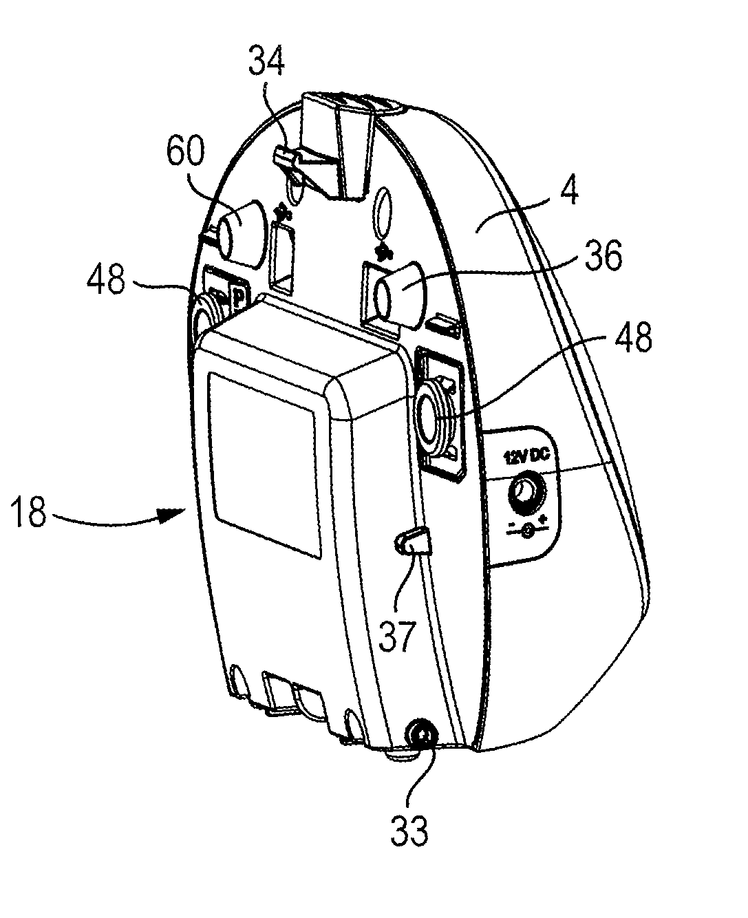
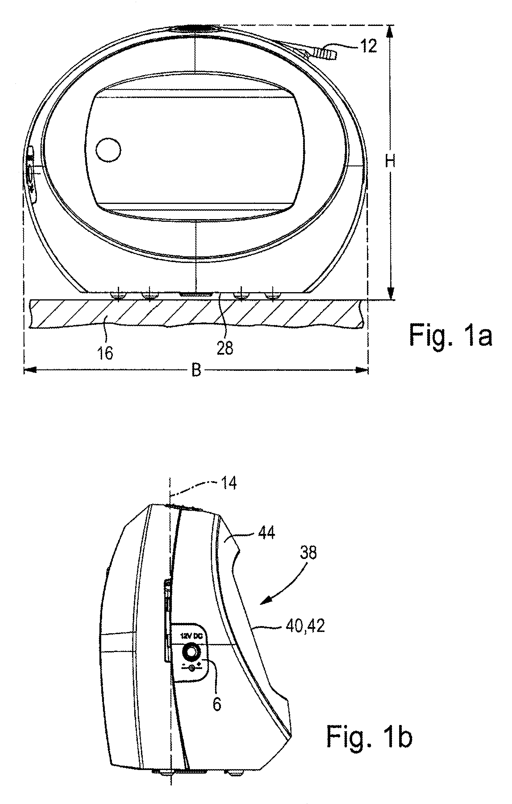
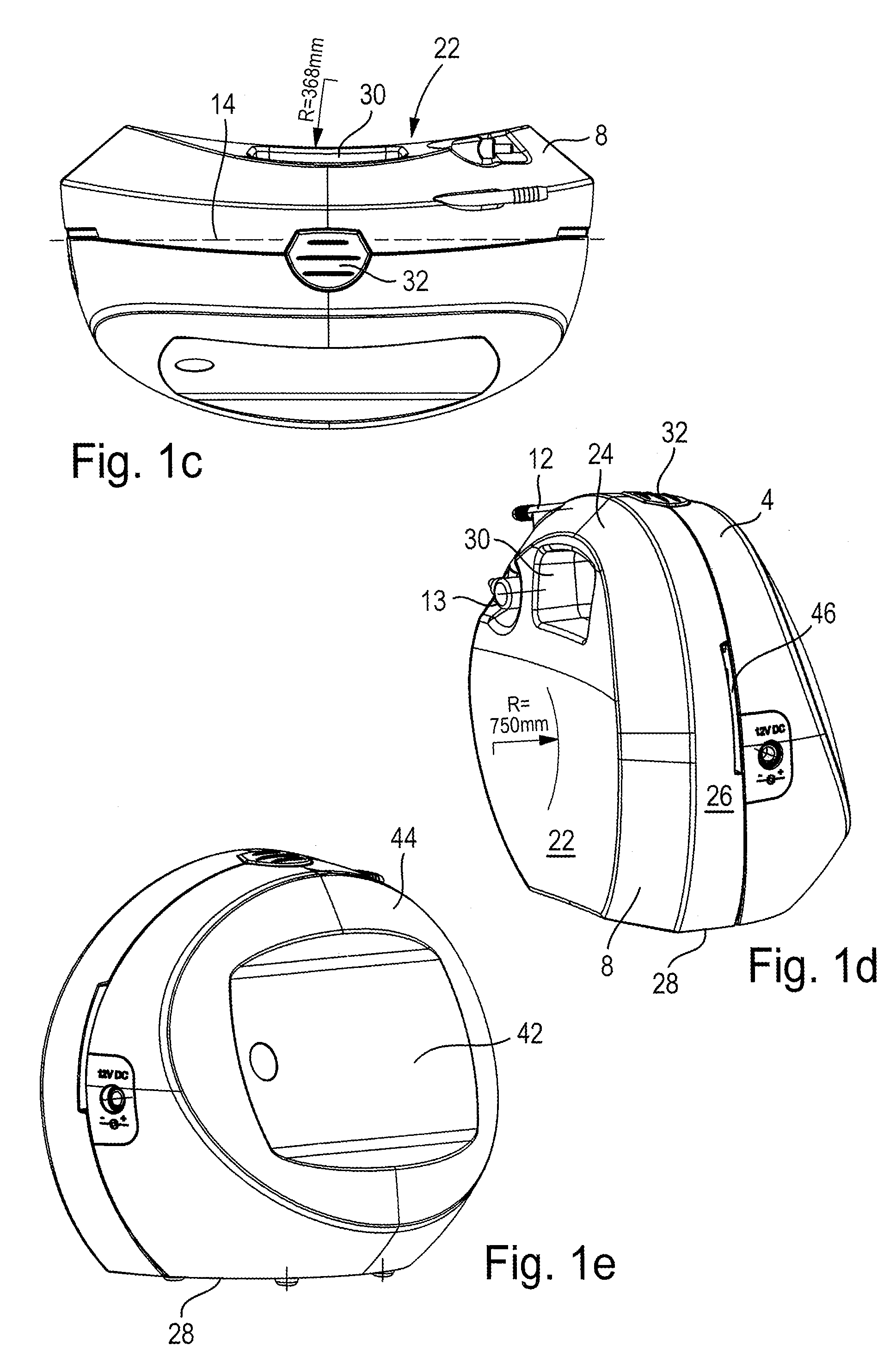
[0029]First, based on FIGS. 1 to 5, two embodiments of a portable device 2 for providing a vacuum for medical applications are described that differ only in respect of their dimensioning and the constitution of a vessel, still to be described, for receiving body liquids. Thereafter, based on FIG. 6, the inventive constitution of the control components of the portable device 2 is described.

[0030]FIGS. 1a to e show a first embodiment of a portable device 2 for the provision of the vacuum for medical applications. The device comprises a first housing part 4 in which a vacuum-producing device in the form of an air suction pump 90 shown in FIG. 6 and electrical and electronic control components for the device are accommodated completely, including batteries or preferably rechargeable batteries. A recharging connection for the batteries is designated by reference symbol 6. Moreover, the device 2 comprises a second housing part 8 that is also a vessel 10 for receiving body fluids, in parti...


PUM


Abstract

A portable device (2) to generate a vacuum for the medical treatment of wounds on the bodies of humans or animals has a vacuum-producing suction pump (90) in a first housing part (4) of the device and a vessel (10) for receiving body liquids. Vacuum is applied for vacuum communication between the suction pump (90), the vessel (10) and a suction tube (82) leading to the body. A pressure sensor (94) measures the pressure in a tube section (88) and a programmable electronic control unit (100) controls the suction pump (90) in dependence on pressure values measured by the pressure sensor (94). The electronic control unit (100) deactivates the suction pump (90) if a rate of change in pressure (Δp / Δt) detected by the pressure sensor (94) exceeds a defined threshold value toward decreasing vacuum.

Description

[0001]This application claims Paris Convention priority of DE 10 2011 075 844.5 filed May 13, 2011 and benefit of Provisional application 61 / 457,845 filed Jun. 17, 2011, the entire disclosures of which are hereby incorporated by reference.BACKGROUND OF THE INVENTION[0002]The invention relates to a portable device suitable for carrying on the body of a user to generate a vacuum for the medical vacuum treatment of wounds on the bodies of humans or animals, comprising a vacuum-producing suction pump in a first housing part of the device, a vessel for receiving body liquids, in particular, wound exudates suctioned out of a wound, wherein the vessel can be releasably attached to the first housing part of the device and a vacuum can be applied by the suction pump in the attached condition, and wherein a connection is provided on the vessel for a suction tube leading to the body, so that vacuum communication between the suction pump, the vessel and the suction tube leading to the body can ...

Claims


Application Information

Patent Timeline
Patent Type & Authority Patents(United States)
IPC IPC(8): A61M1/00
CPCA61M1/0031A61M1/0092A61M1/0084A61M2205/3351A61M2205/3592A61M1/964A61M1/74A61M1/85A61M1/90A61M2209/088A61M1/984
Inventor ECKSTEIN, AXELHOFSTETTER, JUERGEN
Owner PAUL HARTMANN AG
Why Eureka
Try Eureka