Modular implant part and knee joint prosthesis

a technology of knee joint and module, applied in the field of module implants, to achieve the effect of preventing the medullary cavity of the bone and minimizing the risk of damag

Active Publication Date: 2013-09-24
AESCULAP AG
View PDF66 Cites 9 Cited by
  • Summary
  • Abstract
  • Description
  • Claims
  • Application Information

AI Technical Summary

Benefits of technology

[0008]An improved modular implant part of this type enables one to manage without a multiplicity of adapters or shafts in order to connect the implant component to a shaft and implant it in the most varied of implantation dispositions. Due to the translatory movements in a direction transverse or substantially transverse to the longitudinal axis of the shaft that are made possible by means of the connecting device, a lateral displacement of the shaft on the implant component can be established in the desired manner. Different adapters or different shafts for the purposes of mounting on the implant component in differing positions are therefore superfluous. This reduces the manufacturing complexity and thus the costs of the modular implant part on the one hand, whilst increasing the facility of observing the process in an operating theatre on the other, because the operating surgeon can match the modular implant part directly to the anatomy of the respective patient. Thus, in particular, optimal coverage of a partially resected bone by the implant component can be ensured in a simple and safe manner.
[0055]Such a knee joint prosthesis can be matched in an optimal manner to the anatomy of a patient. In particular, it can be designed in such a manner that the implant component ensures maximum coverage of a partially resected bone end.

Problems solved by technology

The disadvantage of the implant parts described in the aforesaid documents is, however, that the shaft can only be mounted on the implant component at defined angular positions or with a defined lateral displacement using appropriate adapters so that, in turn, a multiplicity of appropriate adapters is necessary for different positions of the shaft.

Method used


Image

  • Modular implant part and knee joint prosthesis
  • Modular implant part and knee joint prosthesis
  • Modular implant part and knee joint prosthesis

Examples


Embodiment Construction

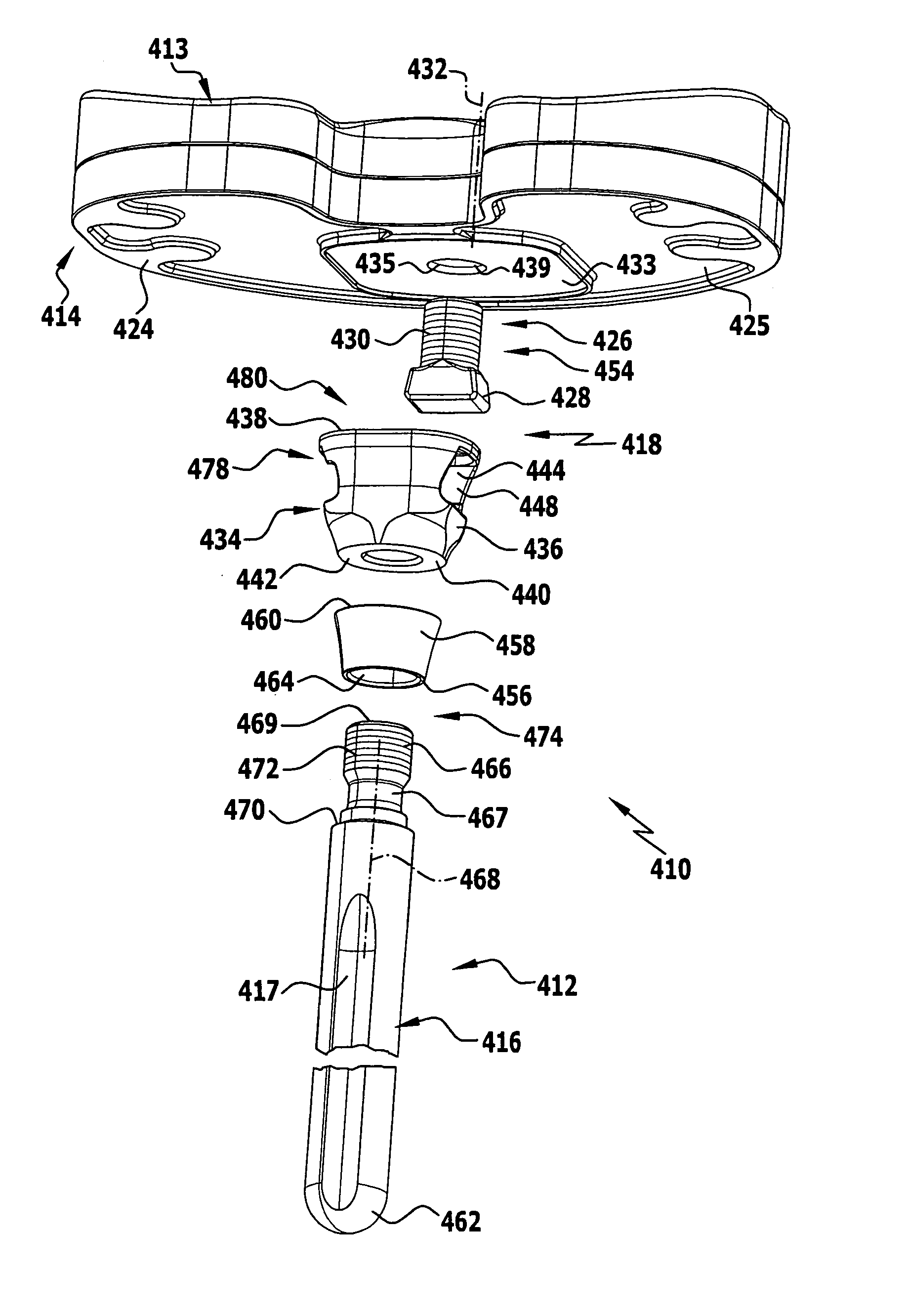
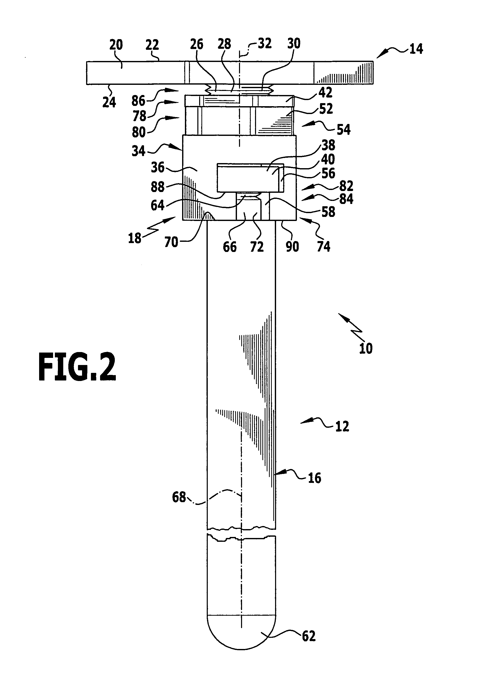
[0070]A first exemplary embodiment of a modular implant part is provided with the general reference symbol 10 in FIGS. 1 to 3. It is illustrated in the form of a tibial part 12 of a knee joint prosthesis which, furthermore, comprises a femoral part and optionally too, a likewise not illustrated meniscus part.

[0071]The implant part 10 comprises an implant component 14, an elongated, round rod-shaped shaft 16 as well as a connecting device 18 for connecting the implant component 14 to the shaft 16.

[0072]The implant component 14 comprises a plate which is substantially kidney-shaped in a top view and forms a tibia plateau 20 the upper surface 22 and lower surface 24 of which are completely flat in the exemplary embodiment illustrated in the Figures. A coupling member 26 in the form of a stud-like projection 28 extends centrally away from the middle of the lower surface 24, this member being provided with an external thread 30 over its entire length. The coupling member 26 is connected ...


PUM


Abstract

In order to improve a modular implant part for replacing a part of a natural knee joint with an implant component comprising a shaft extending away from the implant component and a connecting device for connecting the shaft to the implant component such that the shaft is adapted to be fixed to the implant component in a multiplicity of desired positions in a simple manner, it is proposed that the connecting device be formed in such a manner that, in a mounting disposition, the shaft is adapted to be moved into different translatory positions by a translatory movement in a direction transverse or substantially transverse to its longitudinal axis, and that, in an implantation disposition, the shaft is adapted to be fixed immovably to the implant component in one of the different translatory positions. Furthermore, an improved knee joint prosthesis is proposed.

Description

[0001]The present disclosure relates to the subject matter disclosed in German patent application No. 10 2007 028 087.6 of Jun. 11, 2007 which is incorporated herein by reference in its entirety and for all purposes.BACKGROUND OF THE INVENTION[0002]The present invention relates to a modular implant part for replacing a part of a natural knee joint with an implant component comprising a shaft extending away from the implant component and a connecting device for connecting the shaft to the implant component.[0003]Furthermore, the present invention relates to a knee joint prosthesis comprising a first implant part in the form of a femoral part, a second implant part in the form of a tibial part and a third implant part in the form of a meniscus part, wherein the first and / or the second implant part is a modular implant part for replacing a part of a natural knee joint with an implant component comprising a shaft extending away from the implant component and a connecting device for conn...

Claims


Application Information

Patent Timeline
Patent Type & Authority Patents(United States)
IPC IPC(8): A61F2/38
CPCA61F2/389A61F2/30721A61F2/30734A61F2002/30537A61F2002/30538A61F2250/0008A61F2002/30604A61F2002/30878A61F2250/0004A61F2250/0006A61F2002/30553
Inventor REICH, JANIDLER, UWE
Owner AESCULAP AG
Why Eureka
Try Eureka