Magnetic transmission assembly
a transmission device and magnet transmission technology, applied in the direction of asynchronous induction clutches/brakes, windings, magnetic circuit shapes/forms/construction, etc., can solve the problems of high noise level and heavy weight of mechanical transmission devices, difficult to improve difficult to reduce weight. , to achieve the effect of improving the overall drive power density of motors and transmission devices, improving the drive power density (w/kg or m3) of integrated motor
- Summary
- Abstract
- Description
- Claims
- Application Information
AI Technical Summary
Benefits of technology
Problems solved by technology
Method used
Image
Examples
first embodiment
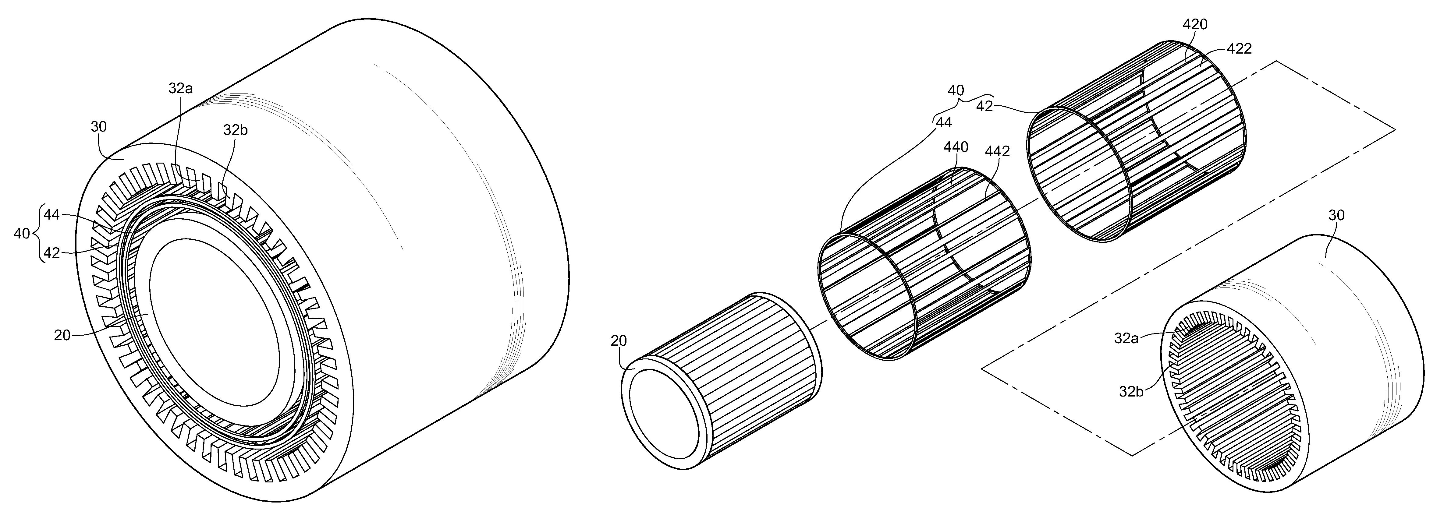
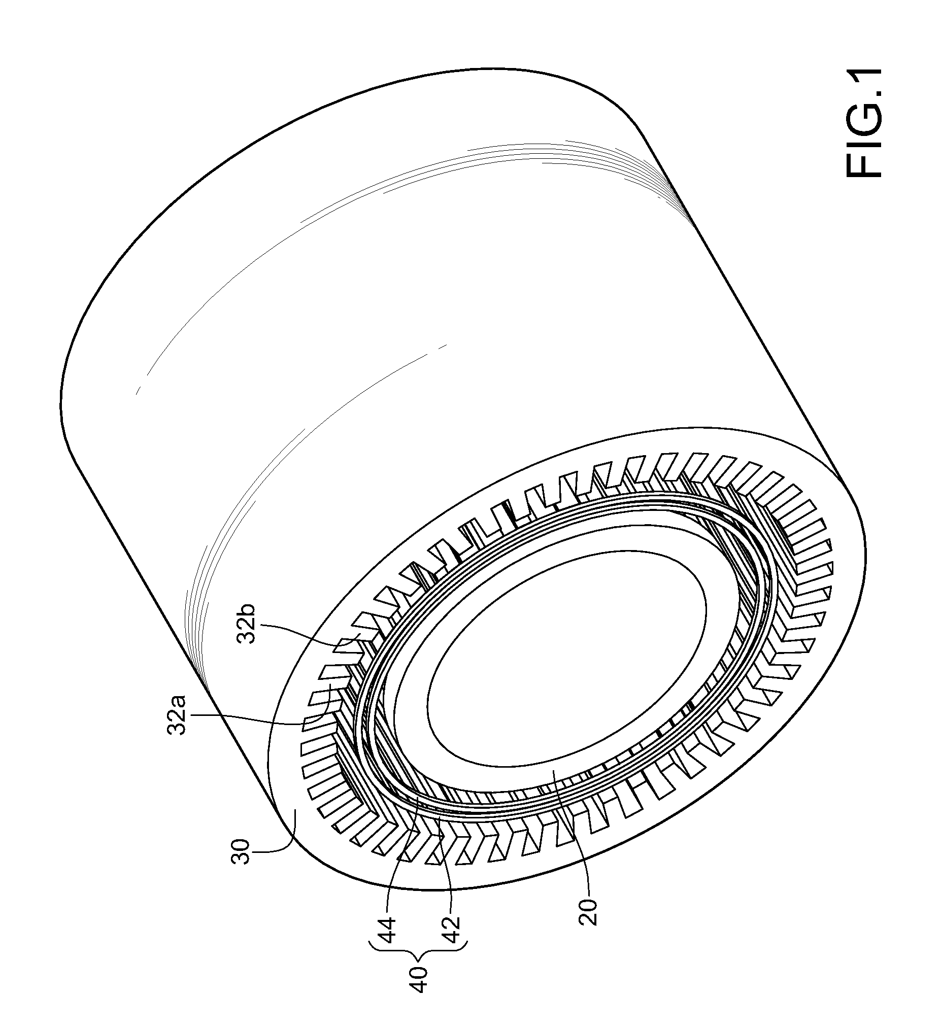
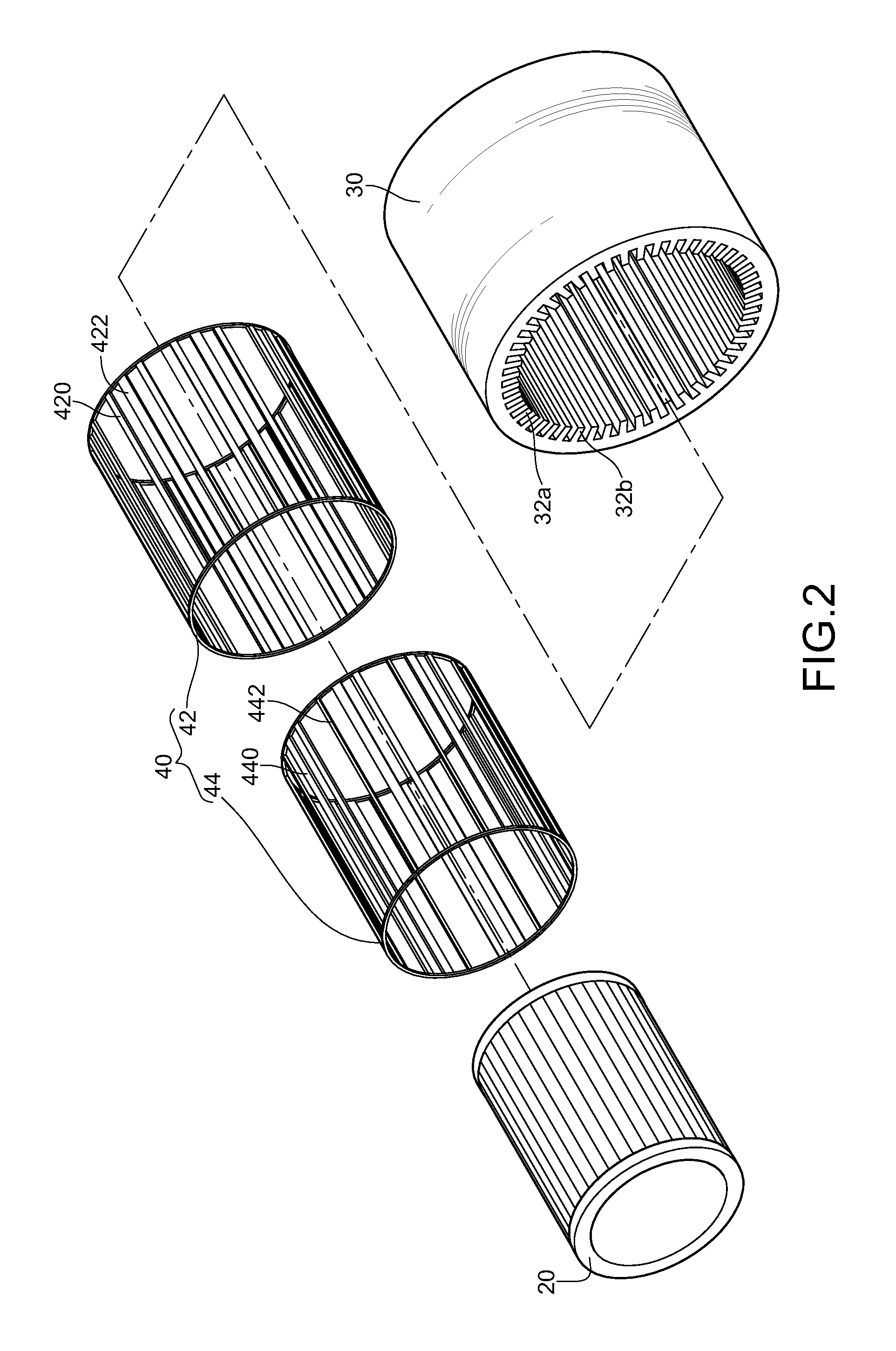
[0042]FIG. 4A is a cross-sectional view of a magnetically conductive element according to an embodiment of the disclosure, which is taken along a plane perpendicular to an axial direction after the first ring 42 is sleeved on the radial outer side of the second ring 44 in FIG. 2. For ease of illustration of the relative rotation of the first ring 42 and the second ring 44, arc segments marked 429 and 449 in FIG. 4A are enlarged in FIG. 4B. The arc segments 429, 449 subtend an angle of 45°, so the first ring 42 and the second ring 44 have 8 arc segments 429, 449 in total. FIG. 4B is a partially enlarged cross-sectional view when the first ring 42 and the second ring 44 are located at the first position. FIG. 4C is a partially enlarged cross-sectional view when the first ring 42 and the second ring 44 are located at the second position.
[0043]As can be seen from FIG. 4B, the permeable block 420 of the first ring 42 and the permeable block 440 of the second ring 44 are in a connection s...
third embodiment
[0063]FIG. 8 is a schematic view of a magnetically conductive element of the magnetic transmission assembly according to the disclosure. The permeable element 60 (or called as magnetically conductive element) comprises a first ring 62 and a second ring 64. The first ring 62 and the second ring 64 are axially connected. The permeable element 60 is disposed between the stator 30 and the rotor 20. The first ring 62 and the second ring 64 are capable of moving axially into the gap between the stator 30 and the rotor 20, such that only one of the first ring 62 and the second ring 64 is sandwiched between the stator 30 and the rotor 20 at a time. In short, when the permeable element 60 is axially actuated, the permeable element 60 selectively enables the first ring 62 or the second ring 64 to be moved to a position between the rotor 20 and the stator 30. As such, the sandwiched first ring 62 or second ring 64 can interact with magnetic fields of the stator 30 and the rotor 20 to generate ...
second embodiment
[0065]Furthermore, please refer to FIG. 9. FIG. 9 is a three-dimensional schematic exploded view of the magnetic transmission assembly according to the disclosure. As can be seen from the figure, a magnetic transmission assembly comprises a rotor 20, a stator 30, and a permeable element 70. The rotor 20 has a plurality of poles and the poles of the rotor 20 have R pole pairs. The stator 30 is sleeved coaxially with the rotor 20 and has a plurality of poles. The poles of the stator 30 have ST1 pole pairs. The permeable element 70 is disposed between the rotor 20 and the stator 30 and has PN1 permeable regions 72. The PN1 permeable regions 72 correspond to the rotor and the stator. PN1−3≦R+ST1≦PN1+3. Accordingly, if R is 20, PN1 is 32 and ST1 is 12, the acceleration ratio or deceleration ratio would be 1.6:1 according to the above Equation (1).
[0066]Next, the two ends of the permeable regions 72 are fixed by two electrical insulating elements 74a, 74b as shown in FIG. 9. By means of d...
PUM
 Abstract
Description
Claims
Application Information
 - R&D
- Intellectual Property
- Life Sciences
- Materials
- Tech Scout
- Unparalleled Data Quality
- Higher Quality Content
- 60% Fewer Hallucinations
Browse by: Latest US Patents, China's latest patents, Technical Efficacy Thesaurus, Application Domain, Technology Topic, Popular Technical Reports.
© 2025 PatSnap. All rights reserved.Legal|Privacy policy|Modern Slavery Act Transparency Statement|Sitemap|About US| Contact US: help@patsnap.com


