Magnetic transmission assembly

a transmission device and magnetoelectric technology, applied in the direction of windings, dynamo-electric brake control, magnetic circuit shape/form/construction, etc., can solve the problems of high noise level and heavy weight of mechanical transmission devices, difficult to improve difficult to reduce weight. , to achieve the effect of improving the overall drive power density of motors and transmission devices, easy integration into electric motors, and increasing the drive power density of integrated motors

Active Publication Date: 2011-09-08
IND TECH RES INST
View PDF38 Cites 0 Cited by
  • Summary
  • Abstract
  • Description
  • Claims
  • Application Information

AI Technical Summary

Benefits of technology

[0016]As mentioned above, the magnetically conductive element is disposed between the stator and the rotor, and the magnetically conductive element is capable of selectively changing the number of the steel pieces (accordingly, also capable of changing the number of magnetic gaps). Accordingly, the magnetic transmission assembly can generates different variable-speed ratios (ratios of the rotation rate of the stator to the rotation rate of the rotor) between the stator and the rotor. Moreover, in another embodiment, the stator is designed to have variable pole pairs, such that different variable-speed ratios can also be achieved by combining the magnetically conductive element with the rotor. The magnetically conductive element, the stator and the rotor may each have a hollow annular shape, such that the entire magnetic transmission assembly has small volume and weight, and can be easily integrated into an electric motor. Consequently, the drive power density (W / Kg or W / m3) of the integrated motor is increased.

Problems solved by technology

The mechanical transmission device has disadvantages of high noise level and heavy weight.
Although the ordinary magnetic transmission device has reduced vibration and noise level, its weight also cannot be reduced.
In such a combination, it is quite difficult to improve the overall drive power density of the motor and the transmission device (due that the total weight of the motor and the transmission device is heavy).

Method used


Image

  • Magnetic transmission assembly
  • Magnetic transmission assembly
  • Magnetic transmission assembly

Examples


Embodiment Construction

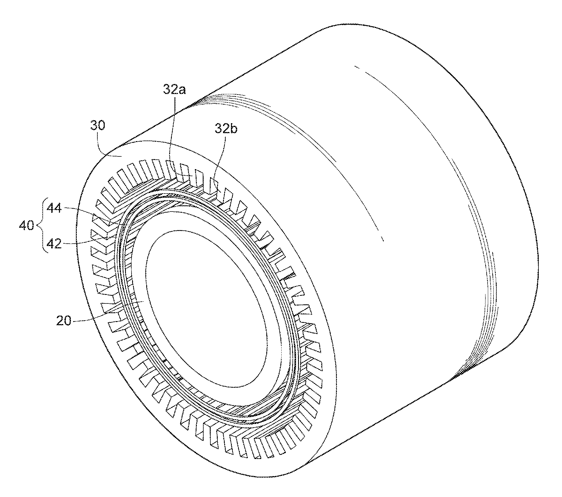
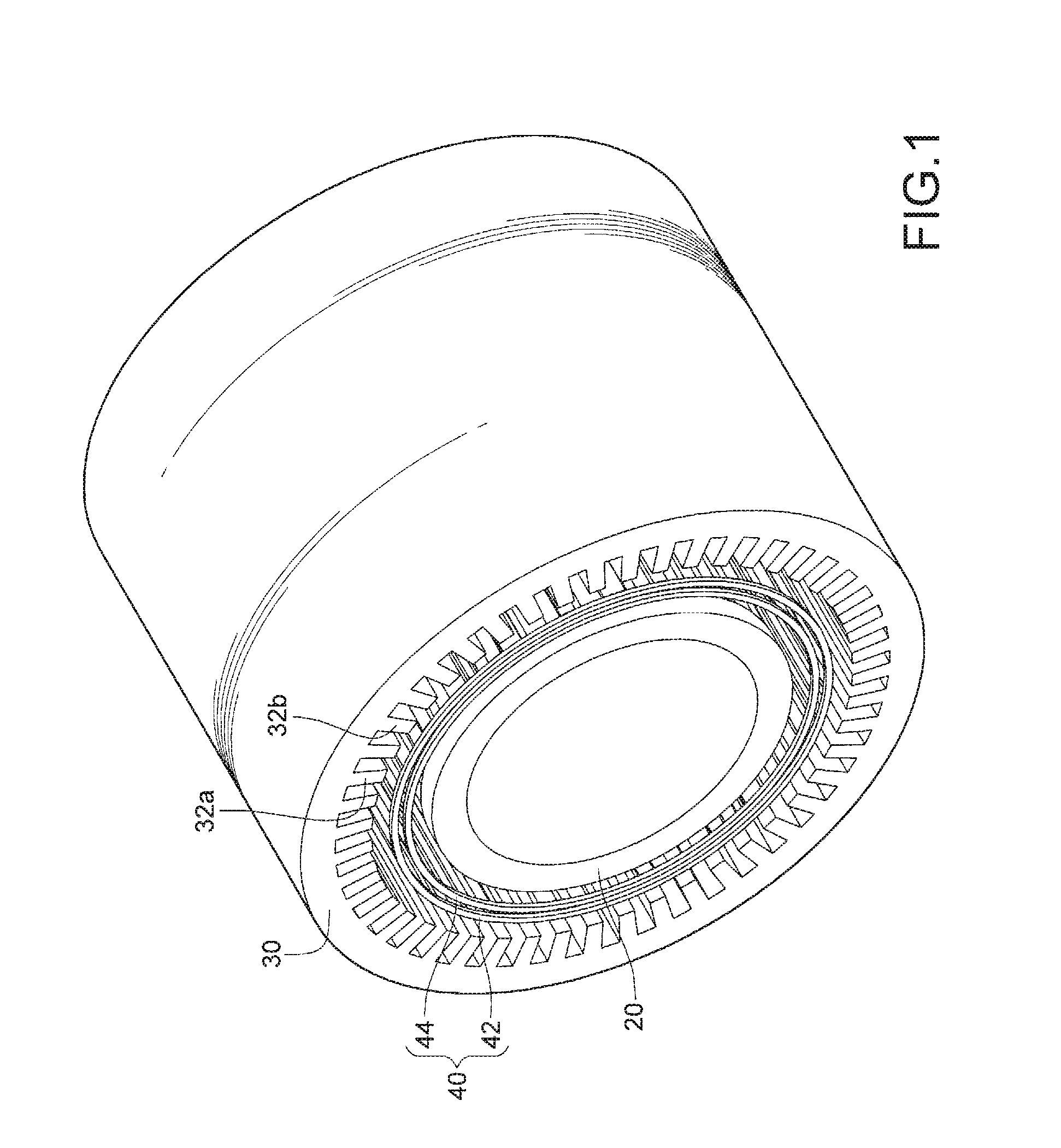
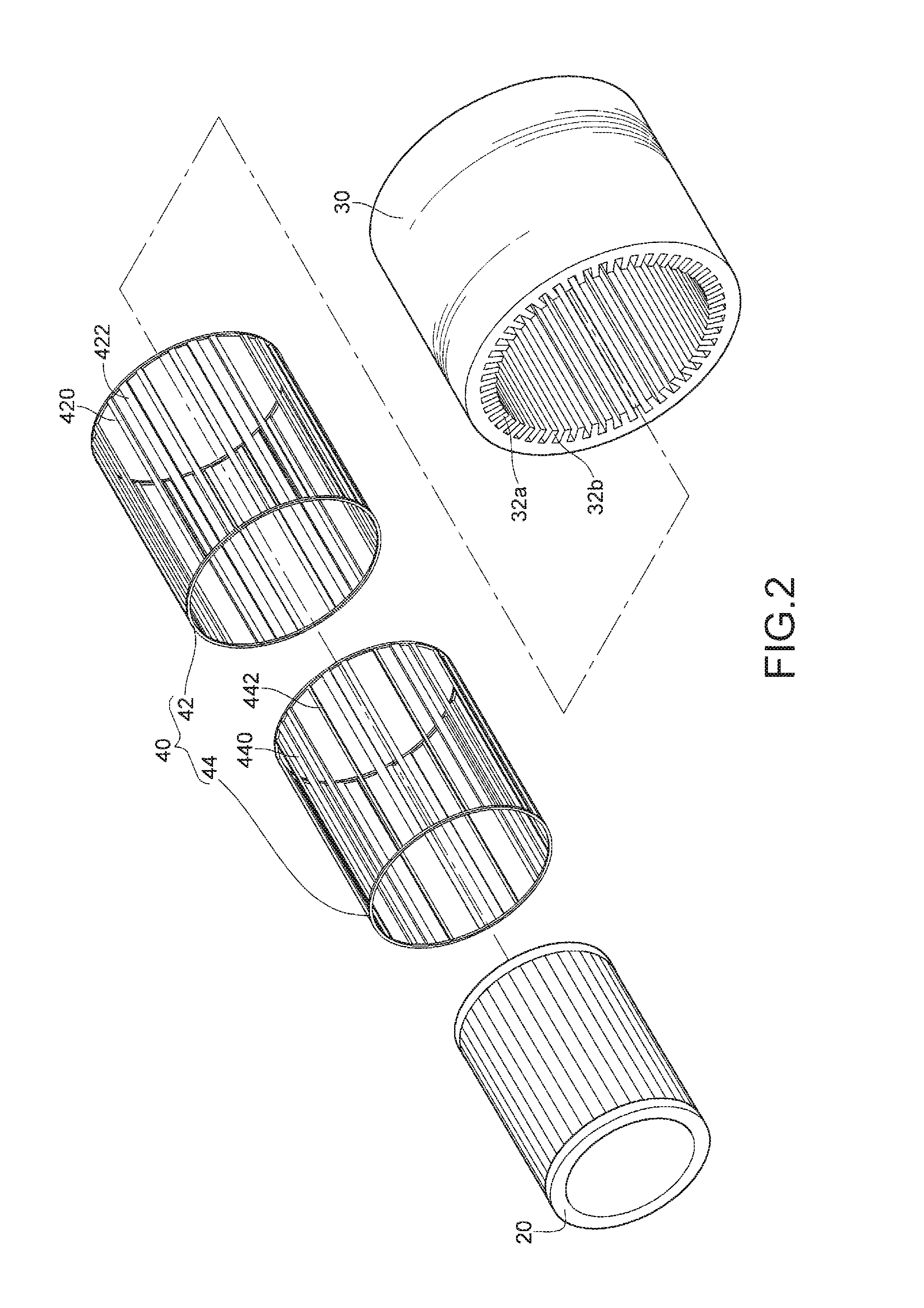
[0031]FIGS. 1 and 2 are respectively a three-dimensional schematic structural view and a three-dimensional exploded view according to an embodiment of the present invention. As can be seen from the figures, a magnetic transmission assembly comprises a rotor 20, a stator 30, and a magnetically conductive element 40 (also referred to as a magnetic transmission element). The magnetic transmission assembly is suitable for integration with a motor (such as an electric motor) or generator. For example, if the magnetic transmission assembly is integrated with an electric motor of an electric automobile, and a motor driver outputs an electromotive force to the magnetic transmission assembly, the magnetic transmission assembly can generate a rotary power at the rotor, and at the same time, the motor driver properly controls the variable-speed ratio of the magnetic transmission assembly, such that the magnetic transmission assembly can output different powers (power=output torque×rotation rat...


PUM


Abstract

A magnetic transmission assembly is adapted to integration with a motor or generator. The magnetic transmission assembly includes a rotor, a stator, and a magnetically conductive element. The rotor and the stator are sleeved coaxially and respectively have R and ST1 pole pairs. The magnetically conductive element is located between the rotor and the stator, and has steel pieces. When the magnetically conductive element is actuated, the magnetically conductive element selectively enables PN1 or PN2 steel pieces to be corresponding to the rotor and the stator. The steel pieces corresponding to the rotor and the stator interact with magnetic fields of the R and ST1 pole pairs to generate a predetermined variable-speed ratio. The magnetic transmission assembly can be integrated into the motor, so as to improve the drive power density.

Description

CROSS-REFERENCE TO RELATED APPLICATIONS[0001]This non-provisional application claims priority under 35 U.S.C. §119(a) on Patent Application No(s). 099106193 filed in Taiwan, R.O.C. on Mar. 3, 2010, the entire contents of which are hereby incorporated by reference.BACKGROUND[0002]1. Field[0003]The present invention relates to a transmission assembly, and more particularly to a magnetic transmission assembly.[0004]2. Related Art[0005]A transmission device not only can be used for power transmission and delivery, but also has the function of accelerating or decelerating the rotation of a power source. Transmission devices applied in conventional automobile engines include mechanical and hydraulic gear boxes. Magnetic transmission devices are applied in electric or hybrid automobiles.[0006]For technologies of variable speed motors, reference is made to U.S. Pat. No. 3,980,937 entitled “Fractional Horsepower Gear Motor” issued on Sep. 14, 1976, in which a power output by a motor is trans...

Claims


Application Information

Patent Timeline
Patent Type & Authority Applications(United States)
IPC IPC(8): H02K49/10
CPCH02K49/10
Inventor PENG, MING-TSANCHENG, LI-JU
Owner IND TECH RES INST
Why Eureka
Try Eureka