Preform for producing plastic containers in a stretch-blow-moulding process

a technology of plastic containers and stretch-blow molding, which is applied in the field of preform, can solve the problems of increasing the overall cost of equipment, unsatisfactory state, and length-stretch ratio

Active Publication Date: 2017-03-07
ALPLA WERKE ALWIN LEHNER
View PDF5 Cites 1 Cited by
  • Summary
  • Abstract
  • Description
  • Claims
  • Application Information

AI Technical Summary

Benefits of technology

[0041]By using a preform without a support ring that can be designed according to the disclosure, the overall costs for the production of plastic containers with any size opening diameters, for example, of plastic bottles, can be reduced in a stretch-blow-molding method. Unlike the preform without a support ring that are known, no specially designed transport means are necessary for transport and no modifications of the mold tools are necessary. In accordance with an exemplary embodiment, the shaping of the preform can result in considerable savings of material, which can be both economically and ecologically beneficial. In addition, the shifting of the center of gravity of the preform in the direction of the preform body achieved by the savings of material in the neck section can prove beneficial in the isolation and correct orientation of the preforms. As a result, lighter preforms or preforms with shorter preform bodies can also be correctly oriented. In addition, special feed systems for stretch-blow-molding plants can be eliminated.
[0047]The embodiment of the plastic container according to the disclosure with a specific material distribution for shifting the center of gravity of the container can be beneficial, for example, also for the stability and the low center of gravity of plastic containers, plastic containers whose container bodies have a non-circular cross-section, for example an oval cross-section. By plastic containers in the neck section that are stretch-blow-molded from the preforms without support rings having less material and therefore a lower weight, the plastic containers can be designed lighter overall or have a container body that can have a greater length relative to the known plastic containers, without thus losing stability and impairing the low center of gravity.

Problems solved by technology

However, this can be unsatisfactory state both from the standpoint of the operator of stretch-blow-molding plants and from the standpoint of the filler of plastic containers produced from the preforms.
With respect to the fact that the grippers engage two areas of the neck area that are opposite to one another and can very easily set a tilting moment depending on the axial position of the contact point, it is immediately clear that grippers that are suitable for the known preform can have a relatively complex structure and therefore greatly increase the overall cost of the equipment.
However, with stretch-blow-molding, this can result in a length-stretch ratio, which can have a negative effect on the strength of the stretch-blow-molded plastic container.
However, the closer the center of gravity of the preform to the support ring or the radial projection, the greater the risk that such preforms can wind up in the wrong position.
This can also result in problems, for example, even in the case of preforms with a large opening diameter and long outside threadings as well as with a small, light preform body.
If the number of erroneously oriented preforms is too large, however, most sorting systems collapse.

Method used


Image

  • Preform for producing plastic containers in a stretch-blow-moulding process
  • Preform for producing plastic containers in a stretch-blow-moulding process
  • Preform for producing plastic containers in a stretch-blow-moulding process

Examples


Embodiment Construction

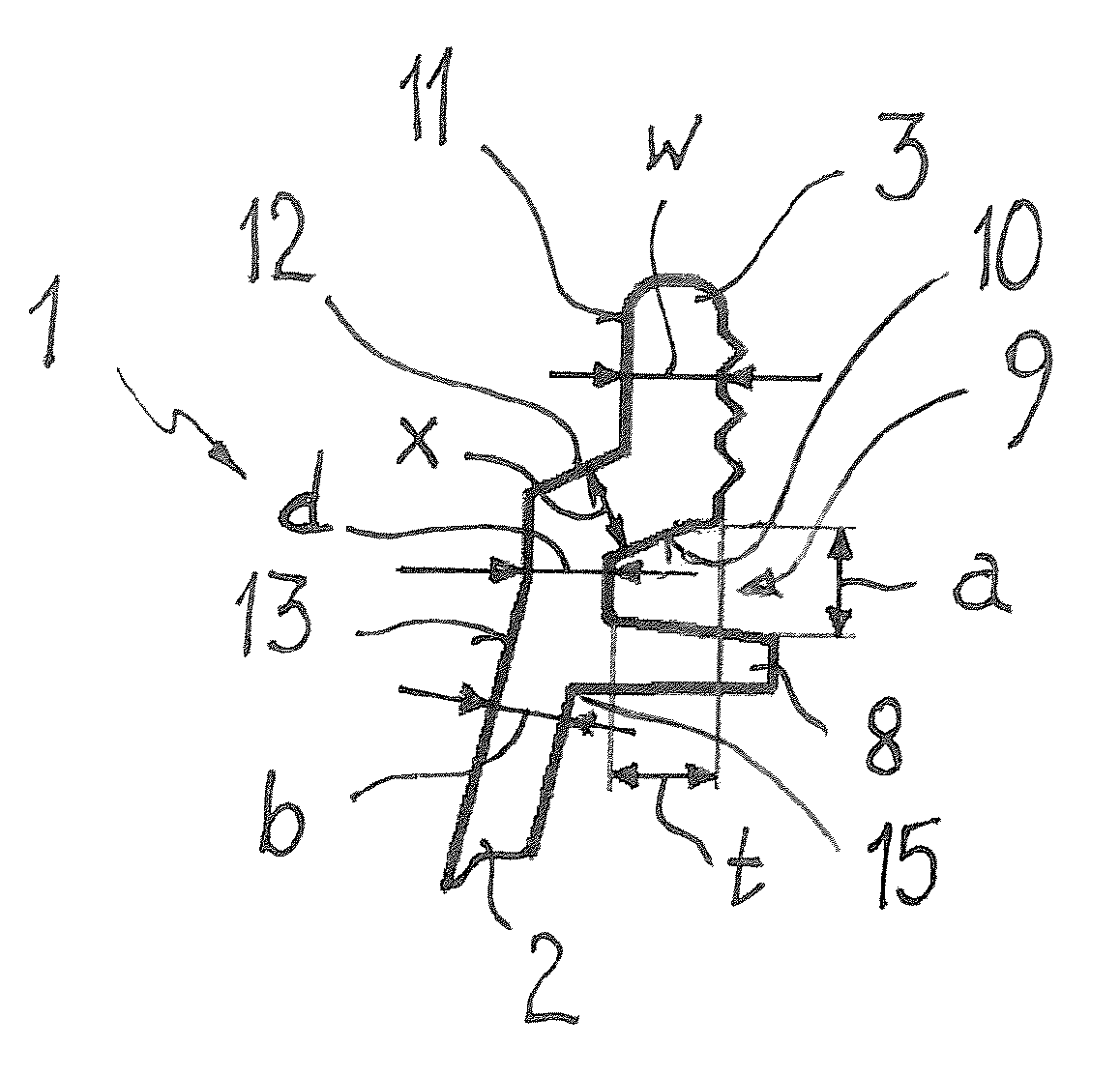
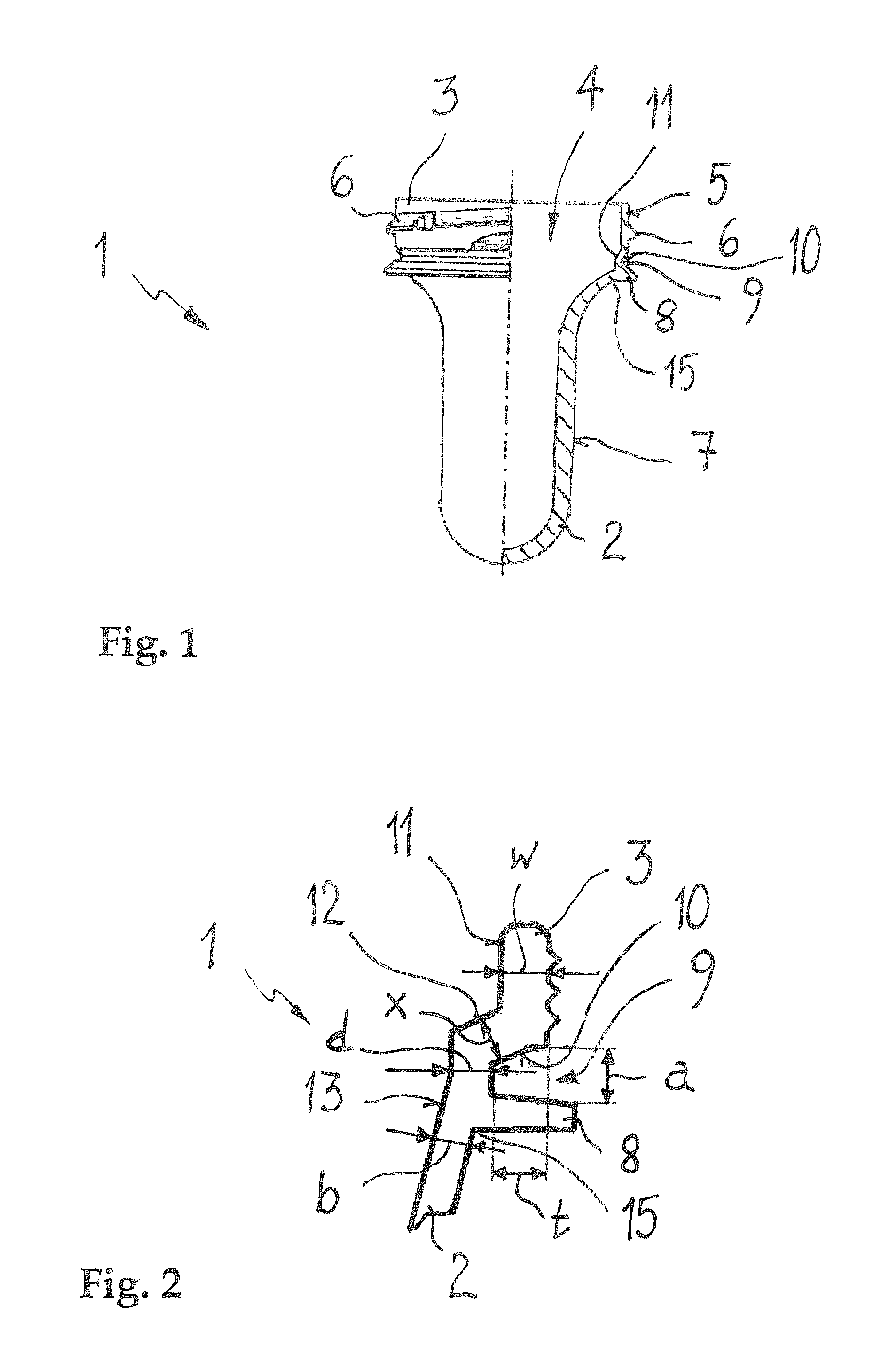
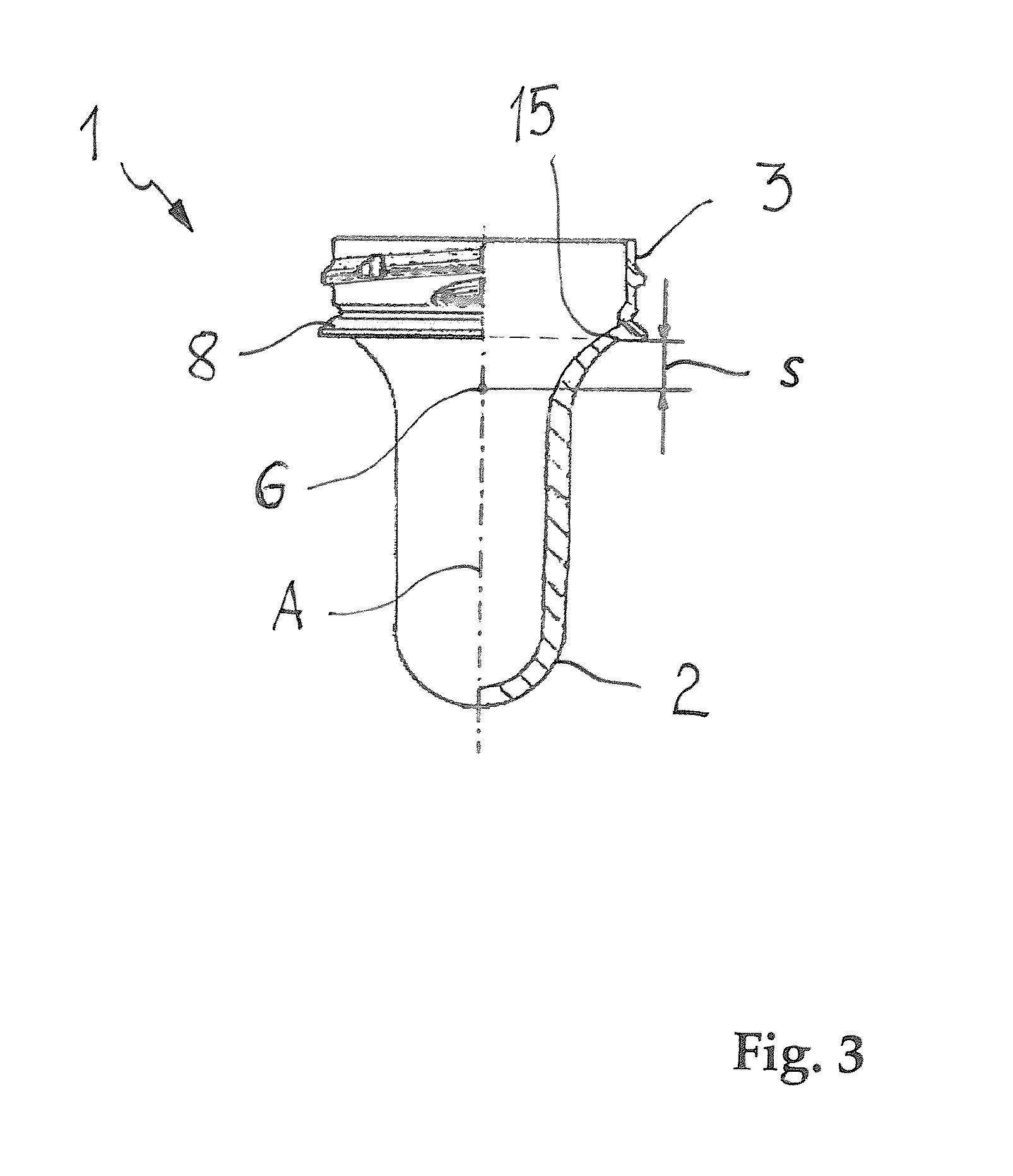
[0018]In accordance with an exemplary embodiment, a preform is disclosed for the production of plastic containers, for example, plastic bottles, in a stretch-blow-molding method, which can reduce the number of erroneously-oriented preforms in sorting and separating devices, for example, in roll sorters. In addition, the amount of material used for the preform can be reduced. The preform can be configured to allow the production of plastic containers with standardized smaller pour openings. In this case, modifications to the stretch-blow-molding plants and to the bottling plants can be avoided. In addition, specially designed grippers for the preforms and the plastic containers produced therefrom can be eliminated. The necessary mechanical strengths and the thermal stability of the plastic containers manufactured from the preforms can remain. In addition, the preform can mass-produce with normal production methods, for example, an injection-molding method, an impact-extruding method,...


PUM

PropertyMeasurementUnit
radial depthaaaaaaaaaa
axial widthaaaaaaaaaa

Abstract

A preform is disclosed for the production of plastic containers, for example plastic bottles, in a stretch-blow-molding method. The preform can include an elongated preform body having a closed longitudinal end and which connects on an opposite longitudinal end to a neck section having a pour opening, the neck section having an outside wall with a fastening means. A rotating flange at a transition from the preform body to the neck section, wherein at least a portion of the rotating flange is annular and radially extends above an outside wall of the preform body. A peripheral annular groove can extend obliquely from a base of the annular groove to the outside wall of the neck section forming a circumferential inner collar, and wherein the inner collar the direction of the preform body, extends axially above the annular groove and extends into an inside wall of the preform body.

Description

RELATED APPLICATION(S)[0001]This application claims priority as a continuation application under 35 U.S.C. §120 to PCT / EP2013 / 002621, which was filed as an International Application on Sep. 2, 2013 designating the U.S., and which claims priority to Swiss Application No. 1648 / 2012 filed in Switzerland on Sep. 10, 2012, and Swiss Application No. 02838 / 12 filed in Switzerland on Dec. 17, 2012. The entire contents of these applications are hereby incorporated by reference in their entireties.FIELD[0002]The disclosure relates to a preform without a support ring for producing plastic containers in a stretch-blow-molding method.BACKGROUND INFORMATION[0003]A large number of plastic bottles and similar plastic containers that are now used can be produced in a stretch-blow-molding process. In this method, a so-called preform of an elongated, tube-like shape, which can have a base on one longitudinal end and a neck section with formed threaded sections or the like on the other longitudinal end...

Claims


Application Information

Patent Timeline
Patent Type & Authority Patents(United States)
IPC IPC(8): B29C49/08B29B11/08B29B11/14B65D1/02B29C49/12B29D22/00B29C49/06B29C49/00B29C49/02B29K23/00B29K25/00B29K27/06B29K67/00
CPCB65D1/0246B29B11/08B29B11/14B29C49/0078B29C49/06B29C49/12B29D22/003B29B2911/1404B29B2911/14013B29B2911/14026B29B2911/14033B29B2911/1444B29B2911/14106B29B2911/14133B29B2911/14326B29B2911/14333B29B2911/14413B29B2911/14473B29B2911/14606B29B2911/14633B29B2911/14726B29K2023/065B29K2023/12B29K2025/06B29K2027/06B29K2067/003Y10T428/1397B29C2949/20B29C2949/3024B29C2949/26B29C2949/28B29C2949/24B29C2949/3032B29C2949/0769B29C2949/073B29C2949/072B29C2949/0813B29C2949/0817B29C2949/0773B29C2949/0831B29C49/071B29C2949/0715B29C2049/023B65D1/02B29C2949/074B29C2949/0778
Inventor SIEGL, ROBERT
Owner ALPLA WERKE ALWIN LEHNER
Why Eureka
Try Eureka