Fuel supply device

a fuel supply device and fuel pressure regulator technology, which is applied in the direction of process and machine control, instruments, cycle equipment, etc., can solve the problems of difficult to combust fuel at the preferred air/fuel ratio in the engine, the mixing ratio is not easily detected, and the predetermined accuracy of detection cannot be obtained by zirconia, so as to increase the air bleed efficiency of the fuel pressure governor, and reduce the amount of air bubbles

Inactive Publication Date: 2013-10-01
HONDA MOTOR CO LTD
View PDF21 Cites 2 Cited by
  • Summary
  • Abstract
  • Description
  • Claims
  • Application Information

AI Technical Summary

Benefits of technology

[0009]An object of the present invention is to provide a fuel feeding device whereby fuel can be combusted at the preferred air / fuel ratio during cold starting of a multi-fuel engine.

Problems solved by technology

In other words, the predetermined accuracy of detection cannot be obtained by the zirconia before the oxygen sensor has reached a predetermined temperature.
The newly filled fuel therefore mixes with the remaining fuel in the fuel tank, and the mixing ratio is not easily detected.
When the predetermined detection accuracy is not obtained, problems occur in that it is difficult to combust fuel at the preferred air / fuel ratio in the engine.

Method used


Image

  • Fuel supply device
  • Fuel supply device
  • Fuel supply device

Examples


first embodiment

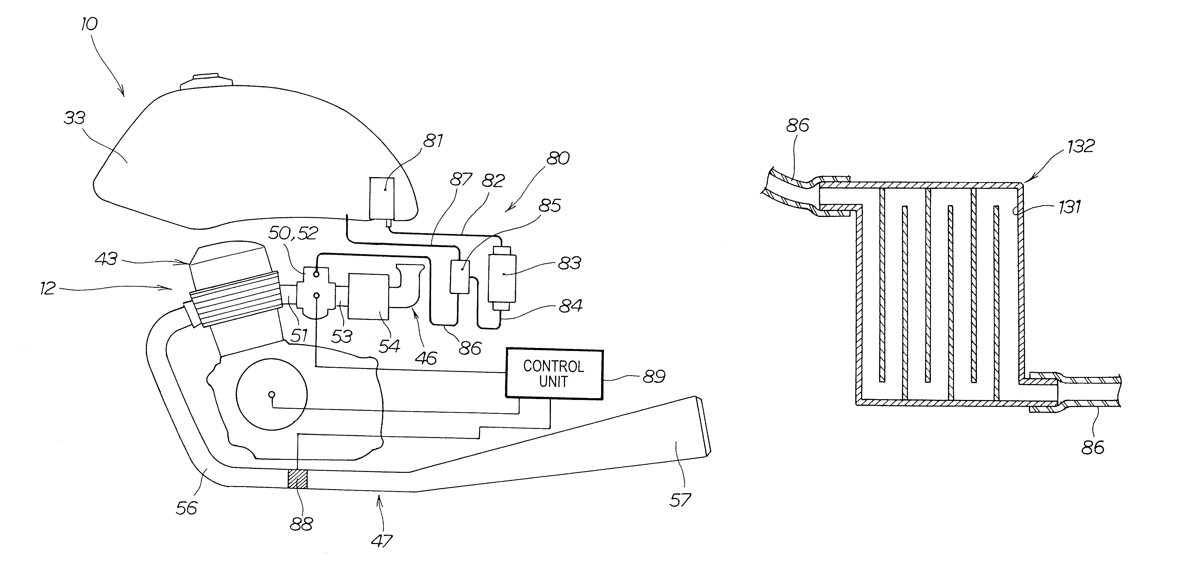
[0096]The reference numeral 82B refers to a feed duct connected between the fuel filter 83B and the fuel pump 81 provided to the fuel tank 33 in the

[0097]Since the connecting line 86B has the coiled part 126, the connecting line 86B can be provided more compactly in the vehicle 10 while maintaining a predetermined fuel volume, compared to a case in which the coiled part 126 is not provided. Providing the connecting line 86B more compactly in the vehicle 10 makes it possible to reduce the amount of space required by the connecting line 86B in the vehicle 10.

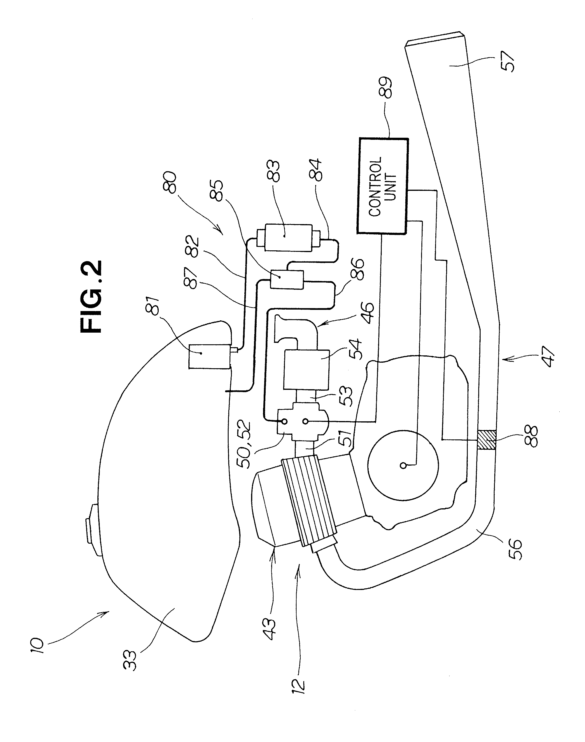
[0098]The volume of the connecting line 86B is a volume equal to or greater than the amount of fuel consumed from startup of the engine 12 (FIG. 2) until the oxygen sensor 88 reaches the measurement-enabling temperature.

[0099]The reference numeral 82B in FIGS. 6 through 8 refers to a feed duct.

[0100]FIG. 9 shows a folded duct part 129 interposed partway in the connecting line. The folded duct part 129 is interposed partway in the ...

fourth embodiment

[0109]FIG. 13 shows the connecting line and surrounding area thereof according to a

[0110]The fourth embodiment differs from the first embodiment with regard to the structure of the fuel pressure governor 85D and the positional relationship between the fuel filter 83D and the fuel pressure governor 85D, and there are no other significant differences.

[0111]In the fuel pressure governor 85D, a fuel hose 84D is connected to the front end part of a horizontally extending shaft part 85Da, a return pipe 87D is connected to the rear end part of the shaft part 85Da, and the fuel pressure governor 85D has a forward-extending part 134 which extends at an angle downward and to the front from a side surface 85Db of the shaft part 85Da and in which a connecting line 86D is connected to the forward-extending part 134.

[0112]The fuel filter 83D is provided so that the axis 83Dj extends in the vertical direction, and the fuel pressure governor 85D is provided toward the outside in the vehicle width d...


PUM


Abstract

A device for feeding fuel from a fuel tank (33) to a multi-fuel engine (12) that uses fuel in which alcohol and gasoline are mixed in an arbitrary ratio. The internal volume of a connecting line (84) provided between a fuel pressure governor (85) and a fuel injection device (50) is a volume equal to or greater than the amount of fuel consumed from startup of the engine until an oxygen sensor (88) reaches a measurement-enabling temperature.

Description

TECHNICAL FIELD[0001]The present invention relates to a device for feeding optimal fuel to a multi-fuel engine that operates using an alcohol / gasoline mixture.BACKGROUND ART[0002]Methods are known for controlling the air / fuel ratio of an engine in accordance with the mixing ratio of alcohol in the fuel in a multi-fuel engine that operates using an alcohol / gasoline mixture, as disclosed in JP-S63-5131-A.[0003]The engine described above is provided with an air intake duct for drawing in outside air, an injector provided in the air intake duct for injecting fuel, an exhaust duct through which exhaust gas passes, and an oxygen concentration sensor (hereinafter referred to as an “oxygen sensor”) for measuring the concentration of oxygen in the exhaust gas, the oxygen sensor being provided in the exhaust duct. A microcomputer computes the optimum air / fuel ratio according to the concentration of oxygen in the exhaust gas, and controls the engine. Specifically, when alcohol is mixed in with...

Claims


Application Information

Patent Timeline
Patent Type & Authority Patents(United States)
IPC IPC(8): F02M55/02F02B13/00
CPCB62J37/00F02M37/0064F02M37/007F02D19/0697F02D19/0678F02D19/084F02D19/088Y02T10/36F02D19/0631Y02T10/30
Inventor YOKURA, YASUFUMIITO, ATSUSHITAKAHASHI, YOICHIIZAKI, TSUYOSHI
Owner HONDA MOTOR CO LTD
Why Eureka
Try Eureka