

Synthesis of liquid fuels from biomass
a technology of biomass and liquid fuel, which is applied in the direction of hydrocarbon oil treatment products, sustainable manufacturing/processing, physical/chemical process catalysts, etc., can solve the problems of slow development progress of new technologies for producing liquid biofuels, high cost of production of these fuels, and net carbon savings
- Summary
- Abstract
- Description
- Claims
- Application Information
AI Technical Summary
Benefits of technology
Problems solved by technology
Method used
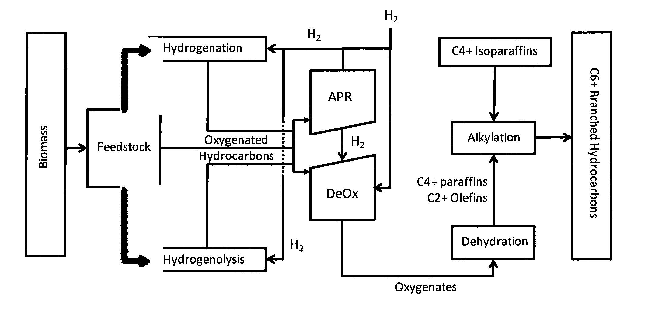
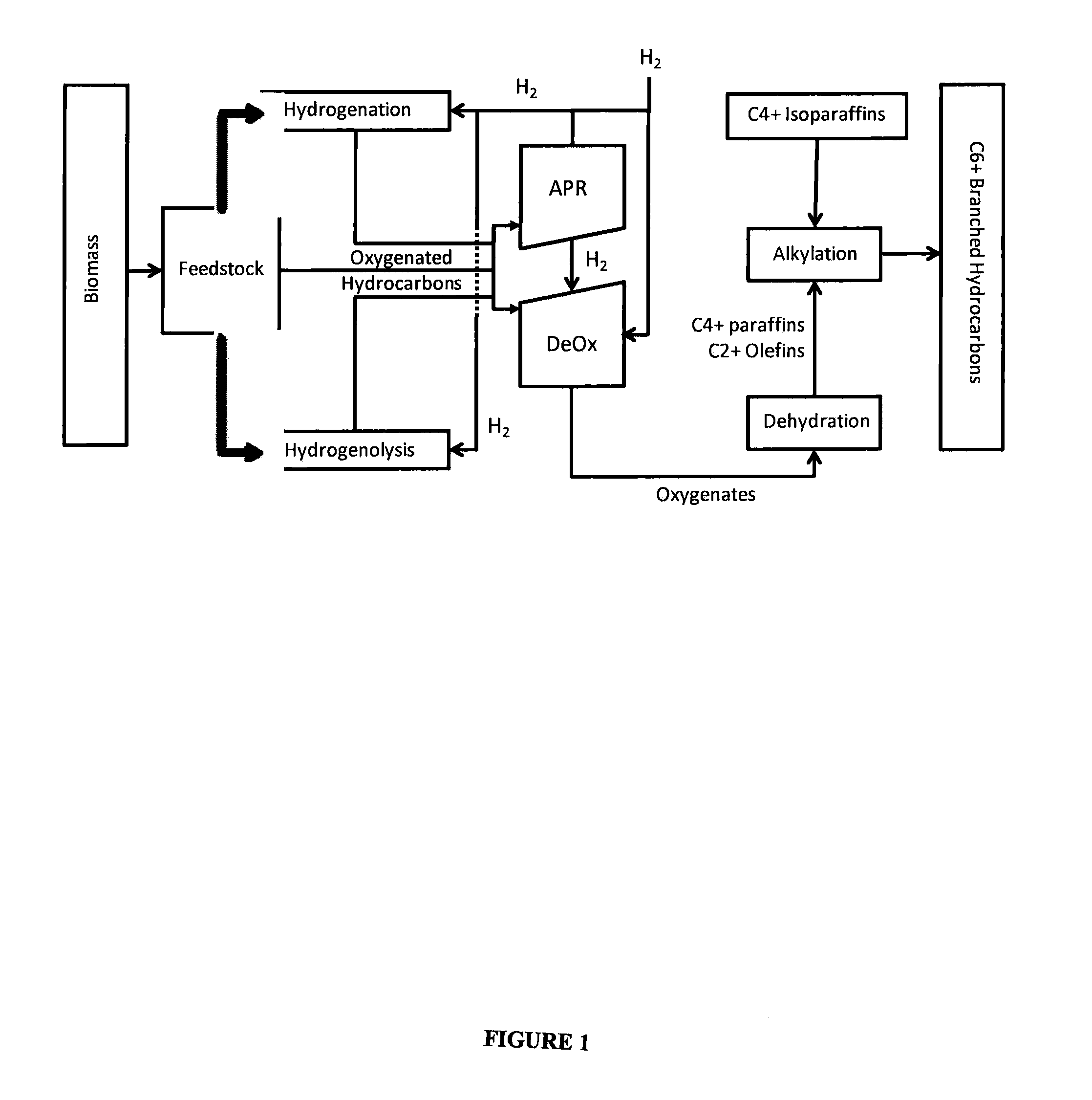
Image

Examples
example 1
APR / Deoxygenation Catalyst
[0155]A combined APR and deoxygenation catalyst was prepared by dissolving hexachloroplatinic acid and perrhenic acid in water and then adding the mixture to a monoclinic zirconia catalyst support (NorPro Saint-Gobain, Product code SZ31164, with particle sizes restricted to those that were maintained on a 60 mesh screen after passing through an 18 mesh screen) using an incipient wetness technique to target a platinum loading of 1.8% and a rhenium loading of 6.3% on the catalyst after subsequent decomposition of the metal precursors. The preparation was dried at 120° C. and subsequently calcined in a stream of flowing air at 400° C.
example 2
Dehydration Catalyst
[0156]An aqueous nickel nitrate solution was added to an alumina bound ZSM-5 zeolite preparation (SiO2:Al2O3 30:1, 3 mm extrudates) using an evaporative impregnation technique to target a nickel loading of 1.0 weight %. The solution volume was three times the incipient wetness volume of the ZSM-5 material: The preparation was dried at 120° C. and then calcined in a stream of flowing air at 400° C.
example 3
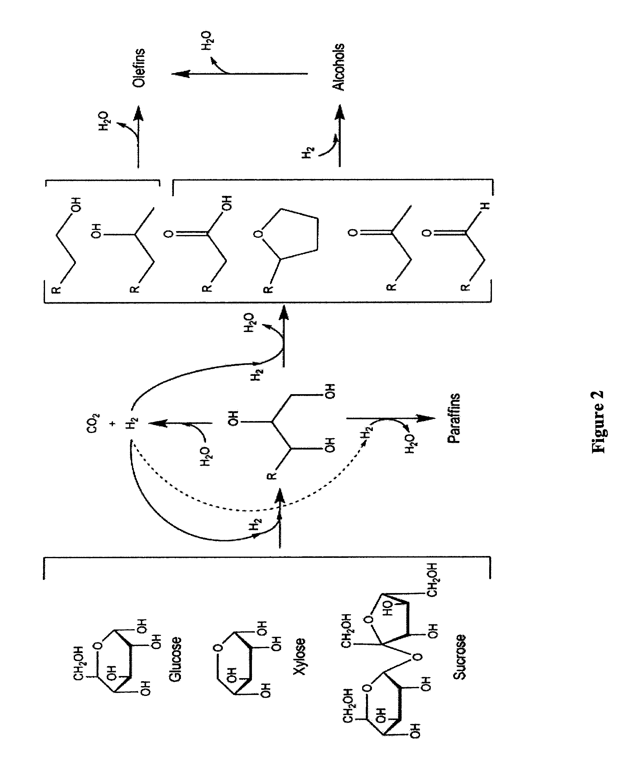
Conversion of Sorbitol to Oyxgenates
[0157]The catalyst system referenced in Example 1 was investigated for the conversion of sorbitol to an intermediate product containing oxygenates using a typical plug flow reactor system. The study was conducted using a 22.1 mm internal diameter Inconel reactor. The reactor pressure was varied between 625 and 1200 psig, while the reactor inlet temperature was varied between 190 and 265° C. The outlet temperature was varied between 185 and 230° C. by adjusting the air flow through a copper coil wrapped around the bottom of the reactor. The partial pressure of hydrogen in the reactor was varied between 625-1200 psig by adjusting the flow rate of the hydrogen stream co-fed with the sorbitol solution and by changing the total system pressure. The sorbitol concentration used was 50 wt %.
TABLE 1Conversion of sorbitol to oxygenates.ExperimentAInlet Temperature (° C.)190-270Outlet Temperature (° C.)185-230Pressure (psig) 625-1200WHSV (wt feed / wt catalyst...
PUM
| Property | Measurement | Unit |
|---|---|---|
| Temperature | aaaaa | aaaaa |
| Pressure | aaaaa | aaaaa |
| Water solubility | aaaaa | aaaaa |
Abstract
Description
Claims
Application Information