
Vehicular air conditioner having two-layered air flow

a technology of air conditioner and air flow structure, which is applied in the direction of vehicle components, railway heating/cooling, vehicle heating/cooling devices, etc., can solve the problems of increasing manufacturing costs due to complicated components, lowering room temperature, and complicated structure, so as to reduce manufacturing costs, facilitate temperature adjustment, and simple structure and operation method

Active Publication Date: 2013-10-01
HANON SYST
View PDF70 Cites 16 Cited by
  • Summary
  • Abstract
  • Description
  • Claims
  • Application Information

AI Technical Summary

Benefits of technology

[0017]The present invention is simple in its structure and operation method, reduces manufacturing costs, and provides easiness in adjustment of temperature since it uses only one temperature control door which adjusts temperature and serves as a separation wall for the two-layer air flow structure.
[0018]Moreover, the present invention can prevent a reduction of an air volume in a cooling mode since a cold air bypass passageway is additionally formed on the downstream side of an evaporator.
[0019]Furthermore, the present invention can prevent an air leakage since it has leak preventing device formed between a side wall of the temperature control door and the inner surface of an air conditioning case.
[0020]In addition, the present invention can improve a sealing efficiency between the air conditioning case and the temperature control door by allowing the upper side edge to be in contact with a partition wall of the air conditioning case, which forms an air passageway, when the air passageway bypassing a heater core is closed, since an auxiliary plate is formed inclinedly with respect to a plate.

Problems solved by technology

That is, the conventional air conditioner for the vehicles introduces cold outdoor air of low humidity thereto since the cold outdoor air is effective to remove frost stained on a window of the vehicle during heating and traveling in the winter season, but it causes lowering of the room temperature.
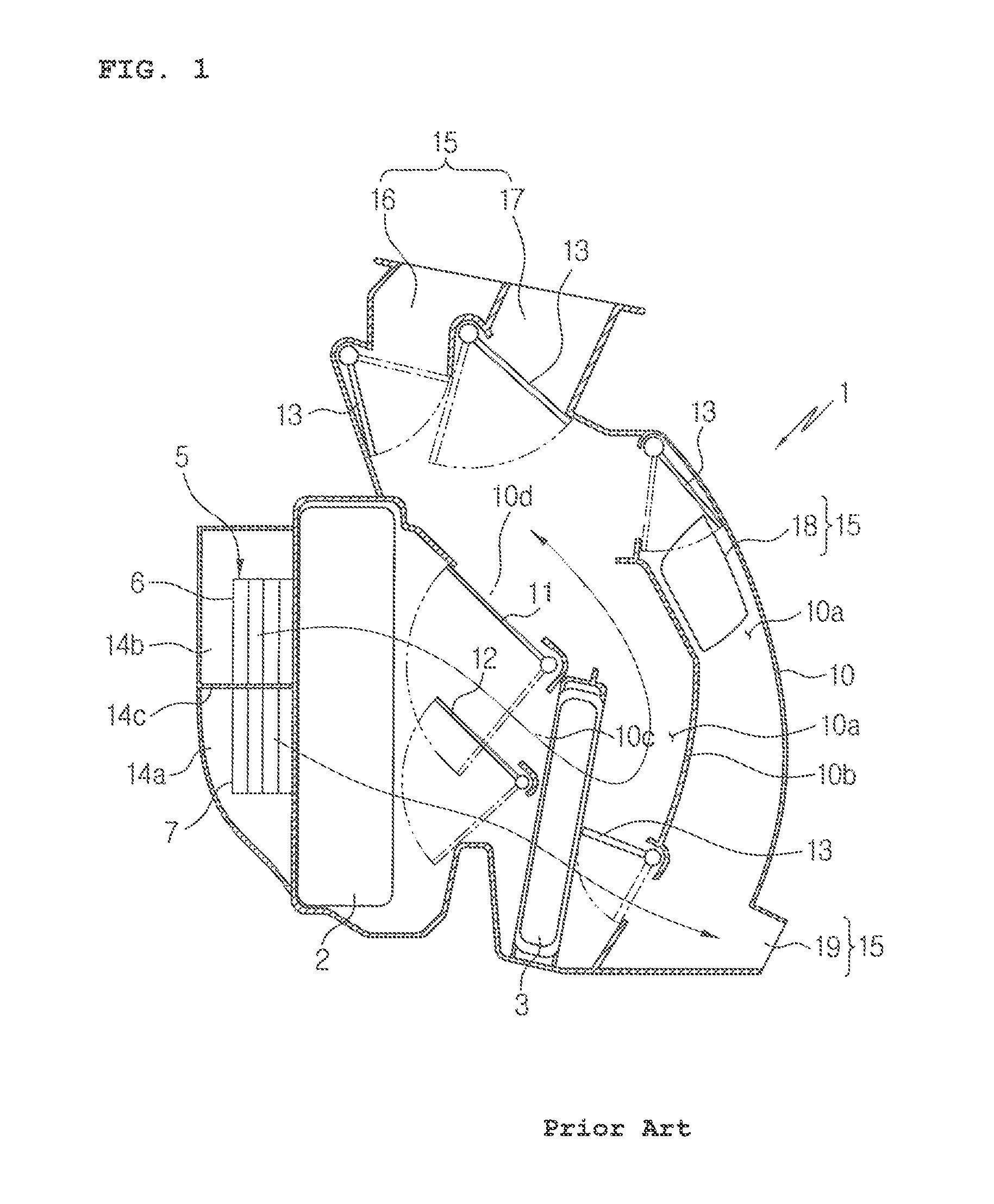
So, the conventional air conditioner 1 has a problem in that its structure is complicated and manufacturing costs are increased due to the complicated components.

Method used


Image

  • Vehicular air conditioner having two-layered air flow
  • Vehicular air conditioner having two-layered air flow
  • Vehicular air conditioner having two-layered air flow

Examples


Embodiment Construction

[0031]Reference will be now made in detail to the preferred embodiment of the present invention with reference to the attached drawings.

[0032]In the present invention, description of the same configuration and action as the prior arts will be omitted.

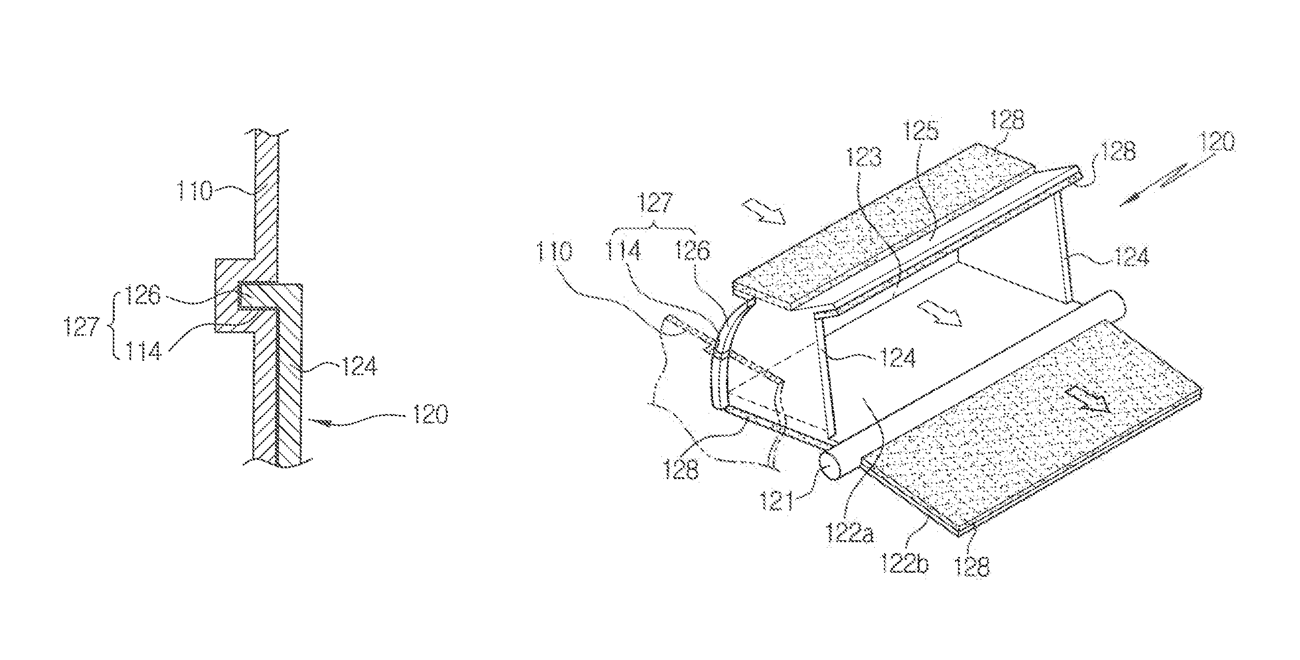
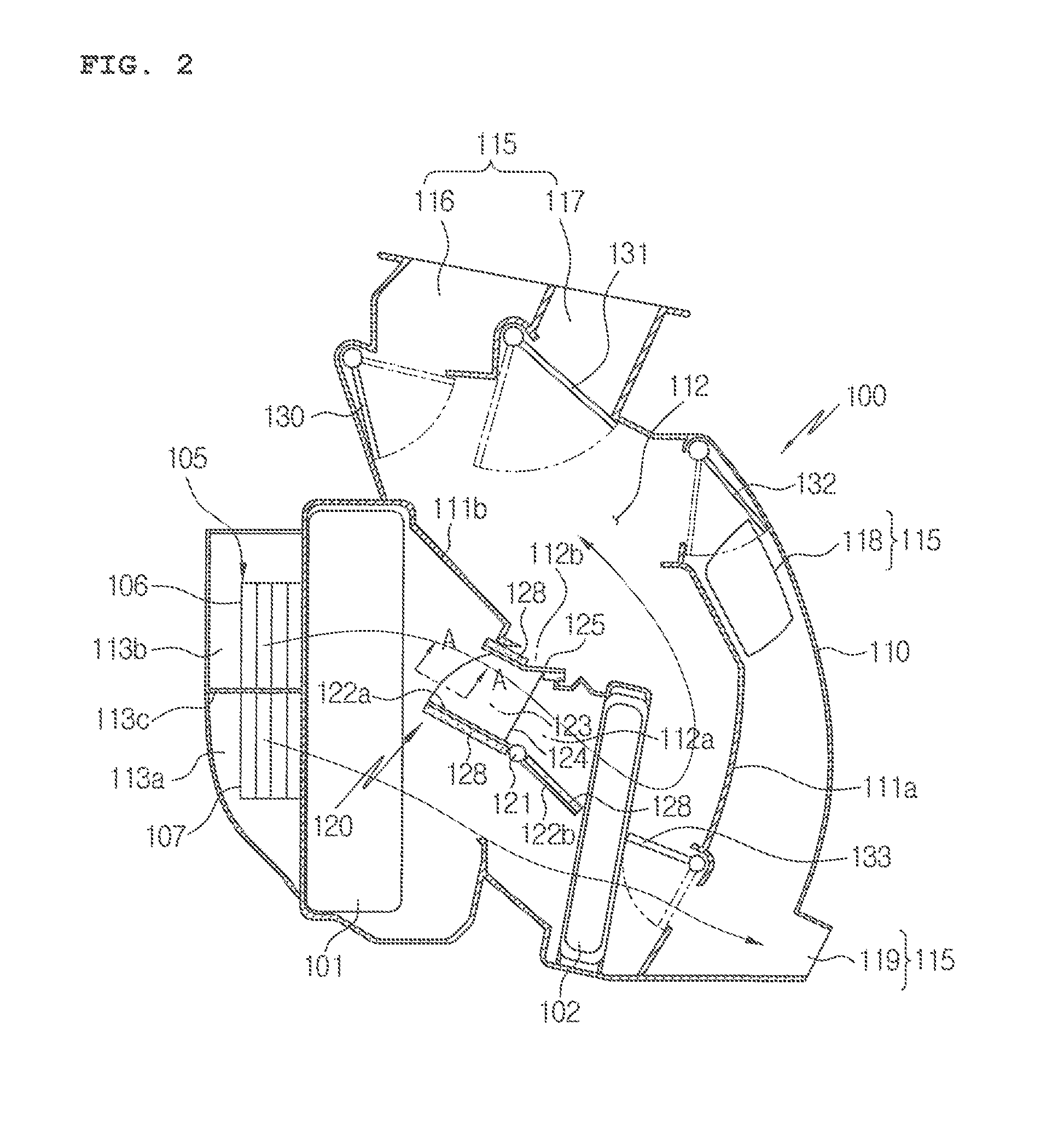
[0033]FIG. 2 is a sectional view of an air conditioner having a two-layer air flow structure according to a first preferred embodiment of the present invention in a two-layer air flow mode, FIG. 3 is a sectional view of an air conditioner having a two-layer air flow structure according to the first preferred embodiment of the present invention in a cooling mode, FIG. 4 is a perspective view of a temperature control door of the air conditioner having the two-layer air flow structure according to the first preferred embodiment of the present invention, FIG. 5 is a sectional view showing a state where a cold air bypass passageway is formed in the air conditioner having the two-layer air flow structure in the cooling mode, FIG. 6 is a secti...


PUM


Abstract

An air conditioner for vehicles having a two layer air flow structure which uses one temperature control door for adjusting the temperature and serving as a partition wall for the two-layer air flow structure.

Description

[0001]This application is a §371 of PCT / KR2006 / 004599 filed Nov. 6, 2006, which claims priority from Korean Patent Application No. 10-2005-0107585 filed Nov. 10, 2005, and Korean Patent Application No. 10-2006-0012041 filed Feb. 8, 2006.TECHNICAL FIELD[0002]The present invention relates to an air conditioner for vehicles having a two layer air flow structure, and more particularly, to an air conditioner having a two-layer air flow structure for vehicles, which uses one temperature control door adjusting temperature and serving as a partition wall for the two-layer air flow structure, thereby reducing manufacturing costs since its structure and operation method are simple, providing easiness in adjusting temperature, and improving sealing efficiency between an air conditioning case and the temperature control door.BACKGROUND ART[0003]In general, an air conditioner for vehicles is a car trim, which is installed in the vehicle in order to secure a driver's front and rear visual field b...

Claims


Application Information

Patent Timeline
Patent Type & Authority Patents(United States)
IPC IPC(8): B60H1/00B60H3/00
CPCB60H1/00064B60H1/00671B60H2001/00721
Inventor LEE, JAEHOON
Owner HANON SYST
Learn More