Envelope power supply calibration of a multi-mode radio frequency power amplifier

a multi-mode radio frequency power amplifier and envelope power supply technology, applied in the field of radio frequency (rf) power amplifiers (pa) circuitry, can solve the problem that the receiver in such a transceiver does not operate simultaneously, and achieve the effect of simplifying calibration requirements, maximizing efficiency of multi-mode rf pa, and minimizing the allowable magnitude of envelope power supplies

Active Publication Date: 2013-10-01
QORVO US INC
View PDF13 Cites 65 Cited by
  • Summary
  • Abstract
  • Description
  • Claims
  • Application Information

AI Technical Summary

Benefits of technology

[0011]By performing the calibration during saturated operation, a maximum power capability of the multi-mode RF PA at each envelope power supply level may be determined. When combined with communications mode specific headroom requirements, the minimum allowable magnitude of the envelope power supply may be determined. As a result, calibrations during linear operation of the multi-mode RF PA may be unnecessary, thereby simplifying calibration requirements. Since efficiency of the multi-mode RF PA may be maximized when the headroom of the envelope power supply is minimized, controlling the envelope power supply to minimize the headroom of the envelope power supply while meeting headroom requirements may optimize the efficiency of the multi-mode RF PA. The multi-mode RF PA may be a multi-mode multi-band RF PA capable of amplifying RF signals in multiple frequency bands. As such, a calibration may be necessary for each frequency band or for certain groupings of frequency bands. However, by performing each calibration during saturated operation, numerous calibrations during linear operations may be avoided, thereby simplifying calibration requirements.

Problems solved by technology

Therefore, the transmitter and receiver in such a transceiver do not operate simultaneously.

Method used


Image

  • Envelope power supply calibration of a multi-mode radio frequency power amplifier
  • Envelope power supply calibration of a multi-mode radio frequency power amplifier
  • Envelope power supply calibration of a multi-mode radio frequency power amplifier

Examples


first embodiment

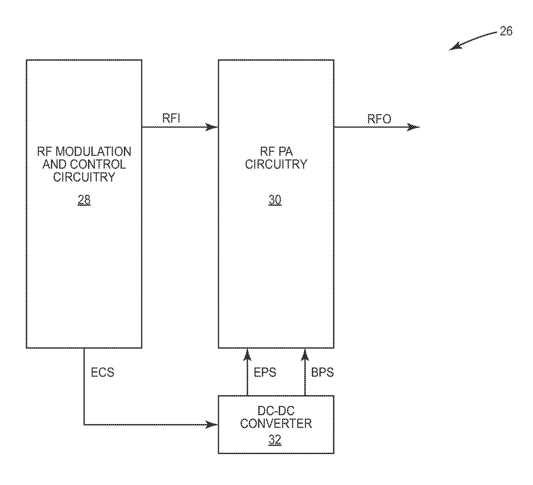
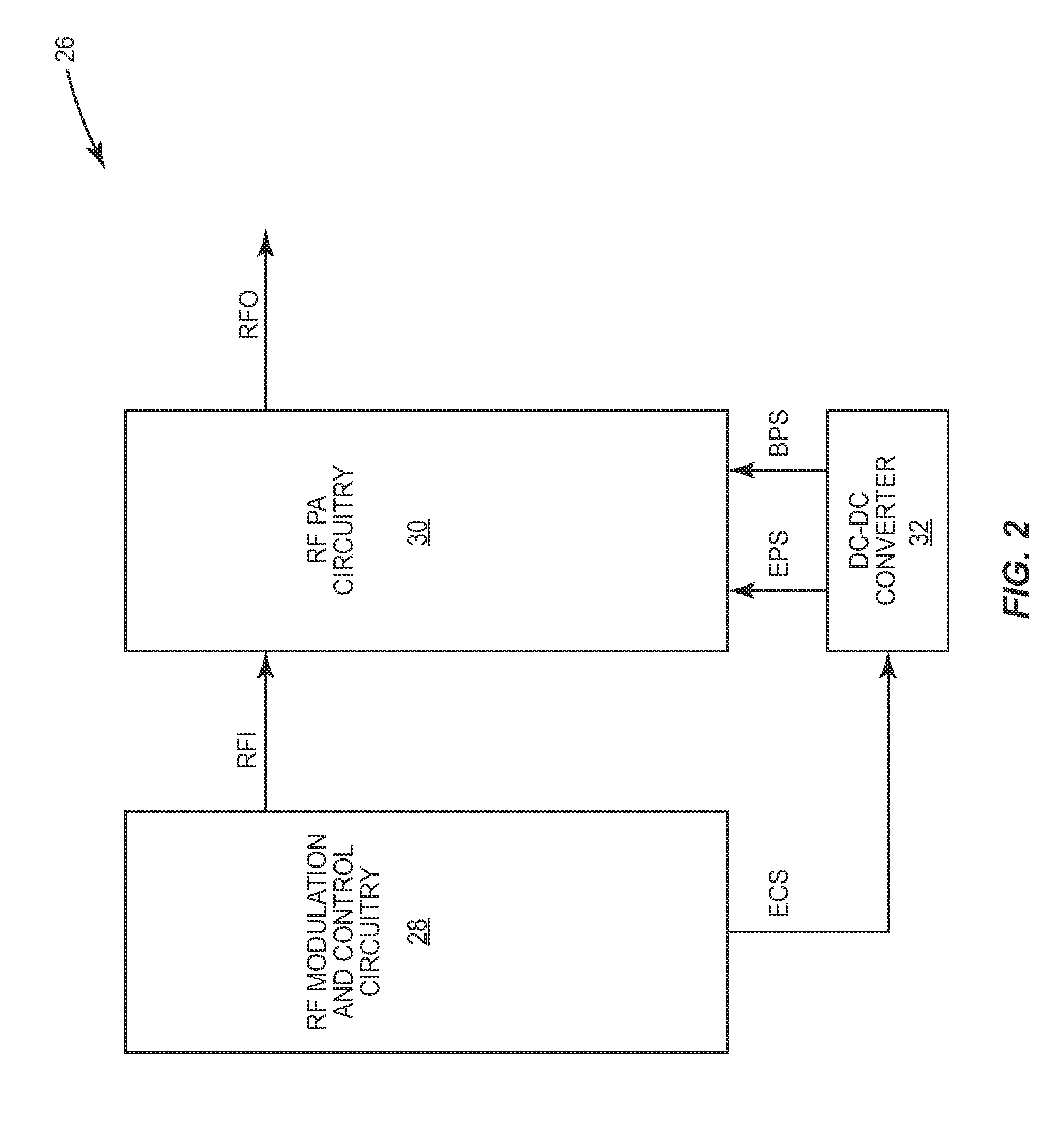
[0061]In the RF communications circuitry 26 (FIG. 3), the RF PA circuitry 30 (FIG. 3) is associated with a first saturation operating constraint. The RF PA circuitry 30 receives and amplifies the first RF input signal FRFI to provide the first RF output signal FRFO and receives the envelope power supply signal EPS, which provides power for amplification. The RF modulation and control circuitry 28 (FIG. 3) selects one of multiple communications modes and determines a desired magnitude of the first RF input signal FRFI. The RF modulation and control circuitry 28 determines a minimum allowable magnitude of the envelope power supply signal EPS based on the first saturation operating constraint, the selected communications mode, and the desired magnitude of the first RF input signal FRFI. The selected communications mode is associated with any offset 90 (FIG. 12) or modulation back-off needed to provide the linearity required for the selected communications mode. The RF modulation and co...

second embodiment

[0063]In the RF communications circuitry 26 (FIG. 3), the RF PA circuitry 30 (FIG. 3) is associated with the first saturation operating constraint. The RF PA circuitry 30 receives and amplifies the first RF input signal FRFI to provide the first RF output signal FRFO and receives the envelope power supply signal EPS, which provides power for amplification. The RF modulation and control circuitry 28 (FIG. 3) selects one of multiple communications modes. The RF modulation and control circuitry 28 determines a maximum allowable magnitude of the first RF input signal FRFI based on the first saturation operating constraint, the selected communications mode, and a magnitude of the envelope power supply signal EPS. The selected communications mode is associated with any offset 90 (FIG. 12) or modulation back-off needed to provide the linearity required for the selected communications mode. The RF modulation and control circuitry 28 limits a magnitude of the first RF input signal FRFI based...


PUM


Abstract

The present disclosure relates to envelope power supply calibration of a multi-mode RF power amplifier (PA) to ensure adequate headroom when operating using one of multiple communications modes. The communications modes may include multiple modulation modes, a half-duplex mode, a full-duplex mode, or any combination thereof. As such, each communications mode may have specific peak-to-average power and linearity requirements for the multi-mode RF PA. As a result, each communications mode may have corresponding envelope power supply headroom requirements. The calibration may include determining a saturation operating constraint based on calibration data obtained during saturated operation of the multi-mode RF PA. During operation of the multi-mode RF PA, the envelope power supply may be restricted to provide a minimum allowable magnitude based on an RF signal level of the multi-mode RF PA, the communications mode, and the saturation operating constraint to provide adequate headroom.

Description

[0001]This application claims the benefit of provisional patent application Ser. No. 61 / 300,089, filed Feb. 1, 2010, the disclosure of which is hereby incorporated herein by reference in its entirety.FIELD OF THE DISCLOSURE[0002]Embodiments of the present disclosure relate to radio frequency (RF) power amplifier (PA) circuitry, which may be used in RF communications systems.BACKGROUND OF THE DISCLOSURE[0003]As wireless communications technologies evolve, wireless communications systems become increasingly sophisticated. As such, wireless communications protocols continue to expand and change to take advantage of the technological evolution. As a result, to maximize flexibility, many wireless communications devices must be capable of supporting any number of wireless communications protocols, including protocols that operate using different communications modes, such as a half-duplex mode or a full-duplex mode, and including protocols that operate using different frequency bands. Fur...

Claims


Application Information

Patent Timeline
Patent Type & Authority Patents(United States)
IPC IPC(8): H03C1/62H04B17/00H04B1/04H01Q11/12
CPCH03G3/3042H03G99/00H03G3/20H04B1/62
Inventor BAXTER, BRIANMILLARD, JASONARKISZEWSKI, ROMAN ZBIGNIEWSELBY, STEVEN
Owner QORVO US INC
Why Eureka
Try Eureka