
Recording tape cartridge

a technology of tape cartridges and cassettes, which is applied in the field of recording tape cartridges, can solve the problems of affecting the ability to easily influence the performance of the rfid tag, so as to achieve the effect of effectively utilizing the space within the cas

Active Publication Date: 2013-10-08
FUJIFILM CORP
View PDF14 Cites 14 Cited by
  • Summary
  • Abstract
  • Description
  • Claims
  • Application Information

AI Technical Summary

Benefits of technology

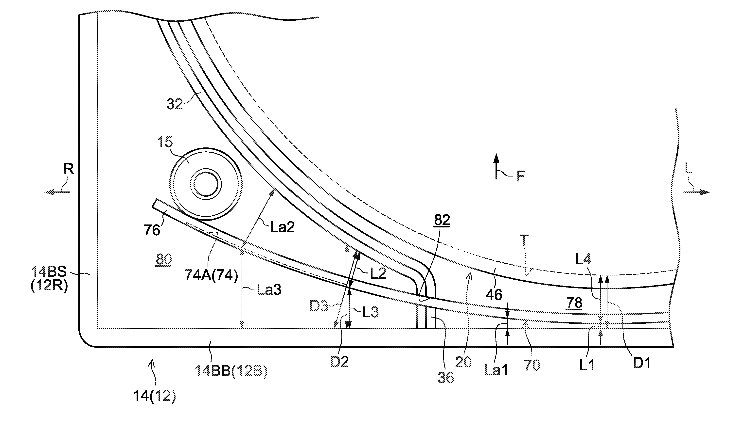
[0018]In the recording tape cartridge of the fifth aspect, at the radiating portion of the antenna, the sum of the distances to the boundary portions that structure the radiating portion space at the both sides in the thickness direction of the radiating portion, is greater than the sum of the distances to the boundary portions that structure the power feed portion space at both sides in the thickness direction of the power feed portion. Namely, the radiating portions are disposed in spaces that are wider in the thickness direction (the normal line direction) than the power feed portion. Here, it is easier for the RFID tag to be affected by the permittivity of the case at the radiating portions than at the power feed portion. Accordingly, by disposing the radiating portions in spaces that are wide in the thickness direction as described above, the RFID tag can be made not to be influenced by the permittivity of the case. On the other hand, because the power feed portion is disposed in a space that is relatively narrow in the thickness direction, the RFID tag is disposed while effectively utilizing the space within the case.
[0028]In the recording tape cartridge of the tenth aspect, the radiating portion spaces are disposed at the outer side of a separating wall that prescribes the reel space. Therefore, the radiating portions that require a needed width (distance between radiating portions) can be easily provided at the outer side of the reel (the reel space) within the case, as compared with a structure in which a space or the like other than the separating wall is disposed between the reel space and the radiating portion spaces.
[0036]In the recording tape cartridge of the thirteenth aspect, a wall, whose permittivity easily affects the radiating portion of the antenna because the wall faces that radiating portion, structures (at least a portion of) the boundary walls that structure the radiating portion space. However, due to the structures of the first aspect, the permittivity of the wall affecting the radiating portion can be effectively suppressed.
[0038]In the recording tape cartridge of the fourteenth aspect, the power feed portion, that is a region at the antenna that is not influenced by the permittivity of the case, is disposed so as to contact a boundary portion that structures the power feed portion space. Therefore, the RFID tag can be disposed by even more effectively utilizing the space within the case.

Problems solved by technology

However, in technologies such as the aforementioned, in cases in which the cartridge case is formed by resin molding, the performance of the RFID tag is affected by the cartridge case (material) that is a dielectric.
Further, because the materials of the magnetic tape, the reel and the like are also considered to be dielectrics, they similarly affect the performance of the RFID tag.
Therefore, the performance of the RFID tag is not influenced by the permittivity of the case easily.

Method used


Image

  • Recording tape cartridge
  • Recording tape cartridge
  • Recording tape cartridge

Examples


second exemplary embodiment

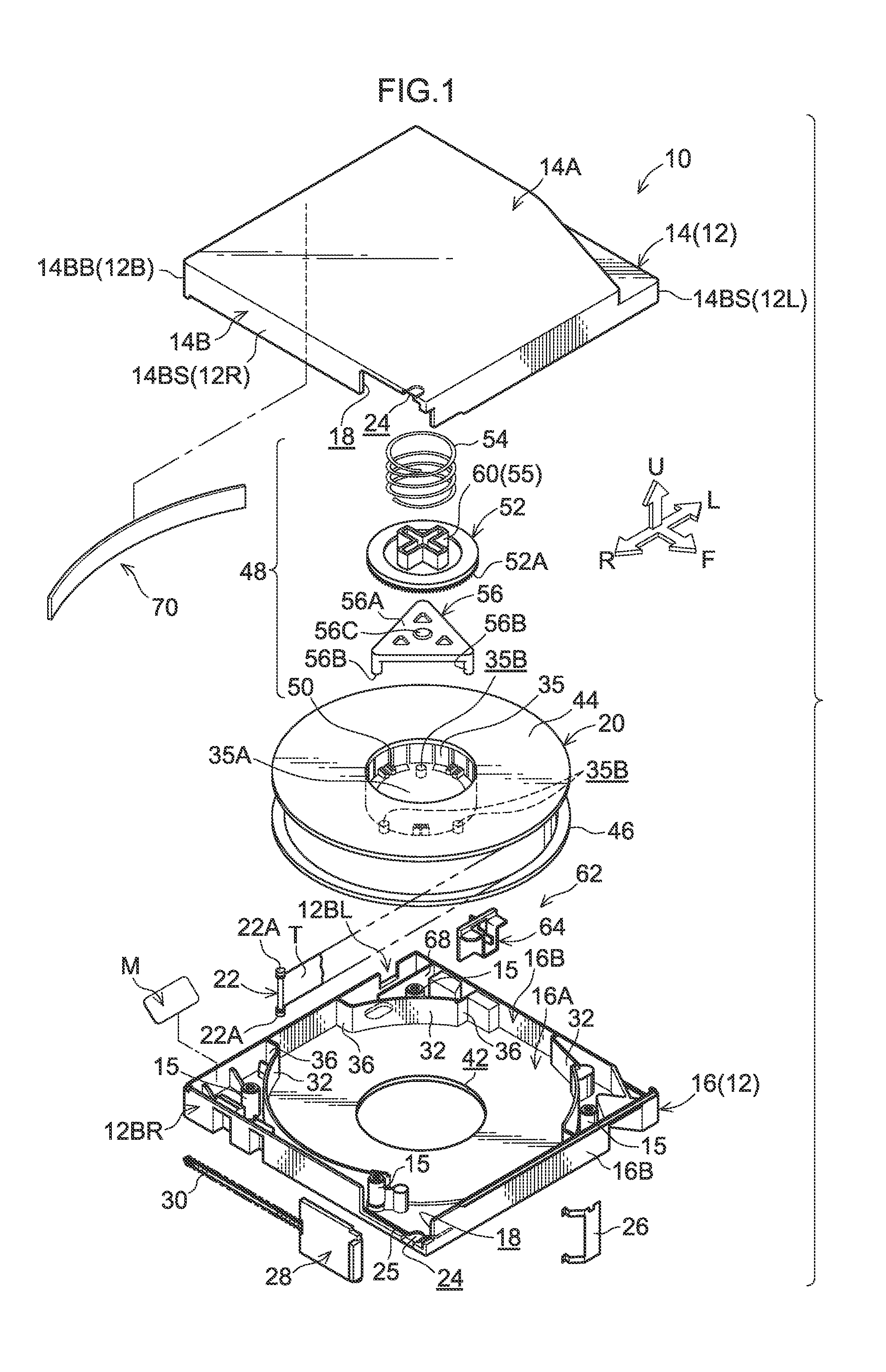
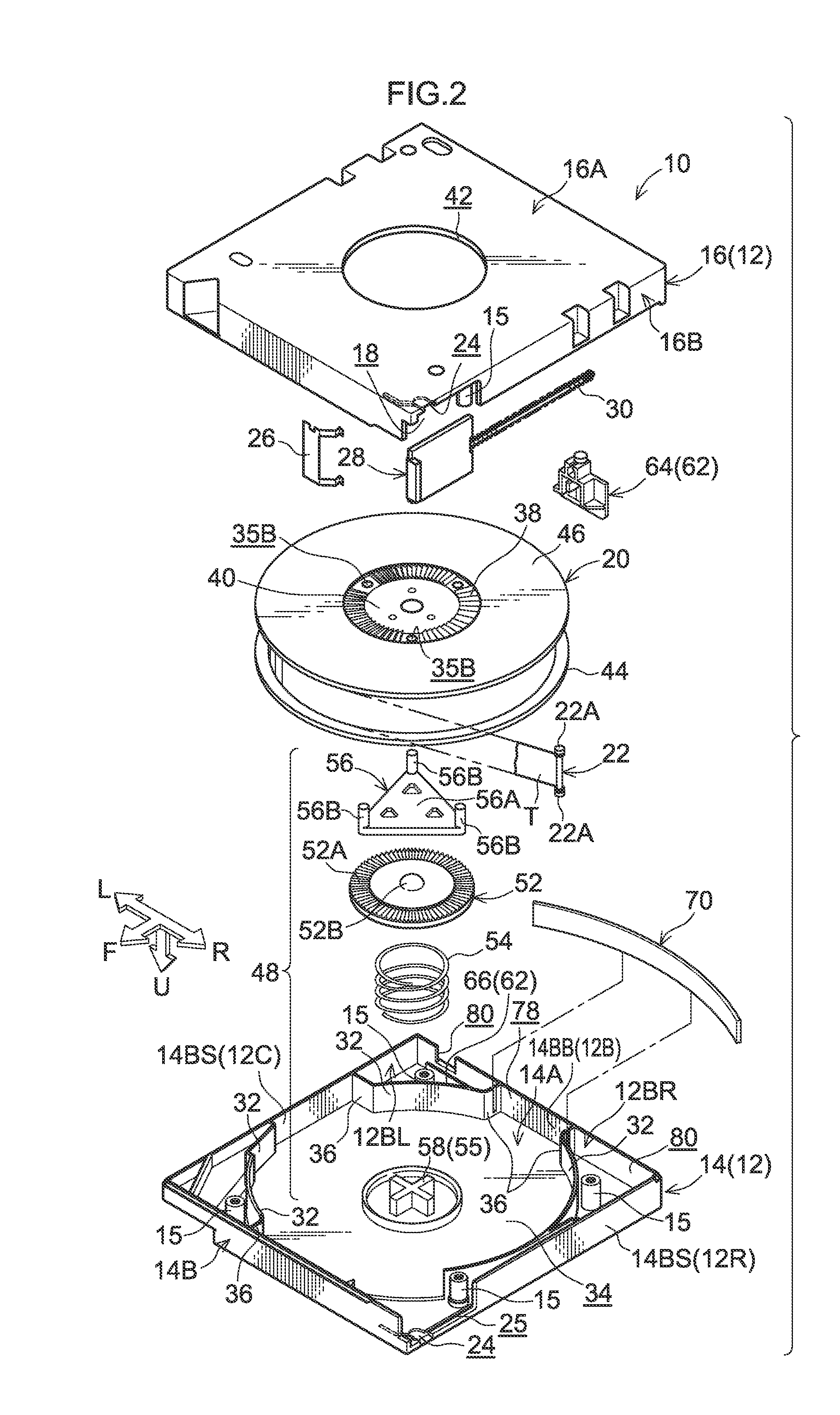
[0128]A second exemplary embodiment of the present invention is described next. Note that parts and portions that are basically the same as those of the above-described first exemplary embodiment are denoted by the same reference numerals as in the first exemplary embodiment, and description thereof is omitted. The exterior of a recording tape cartridge 100 relating to the second exemplary embodiment is shown in a perspective view in FIG. 15. An exploded perspective view of the recording tape cartridge 100 viewed from above is shown in FIG. 14. Note that illustration of the locking mechanism 48 is omitted from FIG. 14. As shown in FIG. 14 and FIG. 15, the recording tape cartridge 100 has a case 102.

[0129]To describe the portions of the case 102 that are different from the case 12, the case 102 is structured by joining together an upper case 114, at which an outer peripheral wall 114B stands downwardly from the peripheral edge of a ceiling plate 114A that is substantially rectangular...


PUM

PropertyMeasurementUnit
widthaaaaaaaaaa
total heightaaaaaaaaaa

Abstract

A recording tape cartridge has: a reel around which a recording tape is wound; a UHF band RFID tag structured to include a tag antenna formed such that radiating portions are disposed at both sides of a power feed portion; and a case in which the reel is housed. Radiating portion spaces, in which are housed regions of the UHF band RFID tag at which the radiating portions are set, and a power feed portion space, in which is housed at least a portion of a region at which the power feed portion is set, are formed within the case at an outer side of a reel space. Regions at which the radiating portions are formed do not contact a reel area rib and a rear upper wall that surround the radiating portion spaces.

Description

CROSS-REFERENCE TO RELATED APPLICATION[0001]This application claims priority under 35 USC 119 from Japanese Patent Application No. 2010-002016, filed Jan. 7, 2010, the disclosure of which is incorporated by reference herein.BACKGROUND[0002]1. Technical Field[0003]The present invention relates to a recording tape cartridge in which an RFID tag is built-in.[0004]2. Related Art[0005]Magnetic tape cartridges, in which an RFID tag is disposed along the inner surface of the rear wall portion of a cartridge case, are known (see, for example, Japanese Patent Application Laid-Open (JP-A) No. 2007-257744).[0006]However, in technologies such as the aforementioned, in cases in which the cartridge case is formed by resin molding, the performance of the RFID tag is affected by the cartridge case (material) that is a dielectric. Further, because the materials of the magnetic tape, the reel and the like are also considered to be dielectrics, they similarly affect the performance of the RFID tag.SUM...

Claims


Application Information

Patent Timeline
Patent Type & Authority Patents(United States)
IPC IPC(8): G11B23/107
CPCG11B23/042G11B23/107
Inventor TADA, NOBUYUKI
Owner FUJIFILM CORP
Learn More