Accessory for a motor-vehicle interior, in particular an armrest for a motor-vehicle seat

a technology for motor vehicles and interiors, which is applied in the direction of wing fasteners, mechanical devices, fastening means, etc., can solve the problems of substantial surface pressure, achieve less demands on clamping surfaces, and facilitate the release of freewheels

Active Publication Date: 2013-10-08
GRAMMER AG
View PDF15 Cites 4 Cited by
  • Summary
  • Abstract
  • Description
  • Claims
  • Application Information

AI Technical Summary

Benefits of technology

[0010]The advantage of the invention is that use of the freewheel configured as per the invention, in particular by the arrangement and forming of the bearing surfaces and counter-surfaces, produces a construction resulting in favorable locking or release performance of the freewheel. The freewheel can also be manufactured particularly cost-effectively. The surface pressure is minimal due to the large-surface contact between the first contact face and the first counter-surface or second contact face and second counter-surface. Demands on the clamping surfaces can therefore be less. For instance, the first counter-surface and / or the second counter-surface can be unhardened. Also, the first and / or the second contact face can be unhardened. In particular the components on which the counter-surfaces are arranged can also be designed for less surface pressure, since the forces are distributed over a larger surface.
[0011]According to a first embodiment, a release device is provided that can move the sprag into the release position. The release device is movable between an active position and a release position. In the active position the sprags can be moved by pivoting of the accessory in the locking position. In the release position the sprags are moved by the release device into the release position. The release device can comprise for example individual release elements that each move a sprag from the locking position into the release position. Actuating the release device can be done for example automatically and / or manually.
[0012]According to another embodiment a counter-surface is formed by a concave inner surface of a substantially cylindrical inner surface of a first component and another counter-surface is formed by a convex outer face of a second component. The surface can be formed for example by a sleeve fixed on the accessory or connected to the accessory. The inner surface of the sleeve can form the concave limiting surface. The convex outer face can be formed for example by a base element fixed in the motor vehicle, which, depending on the number of sprags, forms one or more outer faces. If the freewheel for example has three sprags the base element can comprise three outer faces. The outer faces can be formed by three-dimensional surfaces that can be shaped depending on preferred locking and release performance.
[0013]According to another embodiment the sprag is arranged in a gap formed radially between the first counter-surface and the second counter-surface. The clamping gap is limited by the first counter-surface and the second counter-surface. The clamping gap can taper like a wedge angularly for example with respect to the pivot axis of the accessory. The clamping gap can for example be shaped as a bent wedge. According to another configuration of the invention the sprag is shaped wedge-shaped. If the sprag for example corresponding to the clamping gap is wedge-shaped or bent wedge-shaped, a large first and second contact face on the sprag can be shaped such that is in full surface contact with the counter-surface.
[0014]According to another embodiment the sprag is biased by a spring into the locking position. Due to the biasing of the sprag with a spring a normal force, which generates a friction force, can be exerted constantly on the first and / or the second counter-surface.
[0015]Another embodiment is characterized in that a coefficient of friction of 0.8<FR is provided between the first contact face and the first counter-surface. With relatively minimal normal force a relatively high friction force is generated due to the large coefficients of friction. The sprag is also moved by a high coefficient of friction at minimal normal force due to the resulting friction force from the equipping part. The normal force can be generated for example by a spring.

Problems solved by technology

In the locking position, substantial surface pressures therefore result from the freewheels from the prior art on the first and second counter-surface.

Method used


Image

  • Accessory for a motor-vehicle interior, in particular an armrest for a motor-vehicle seat
  • Accessory for a motor-vehicle interior, in particular an armrest for a motor-vehicle seat
  • Accessory for a motor-vehicle interior, in particular an armrest for a motor-vehicle seat

Examples


Embodiment Construction

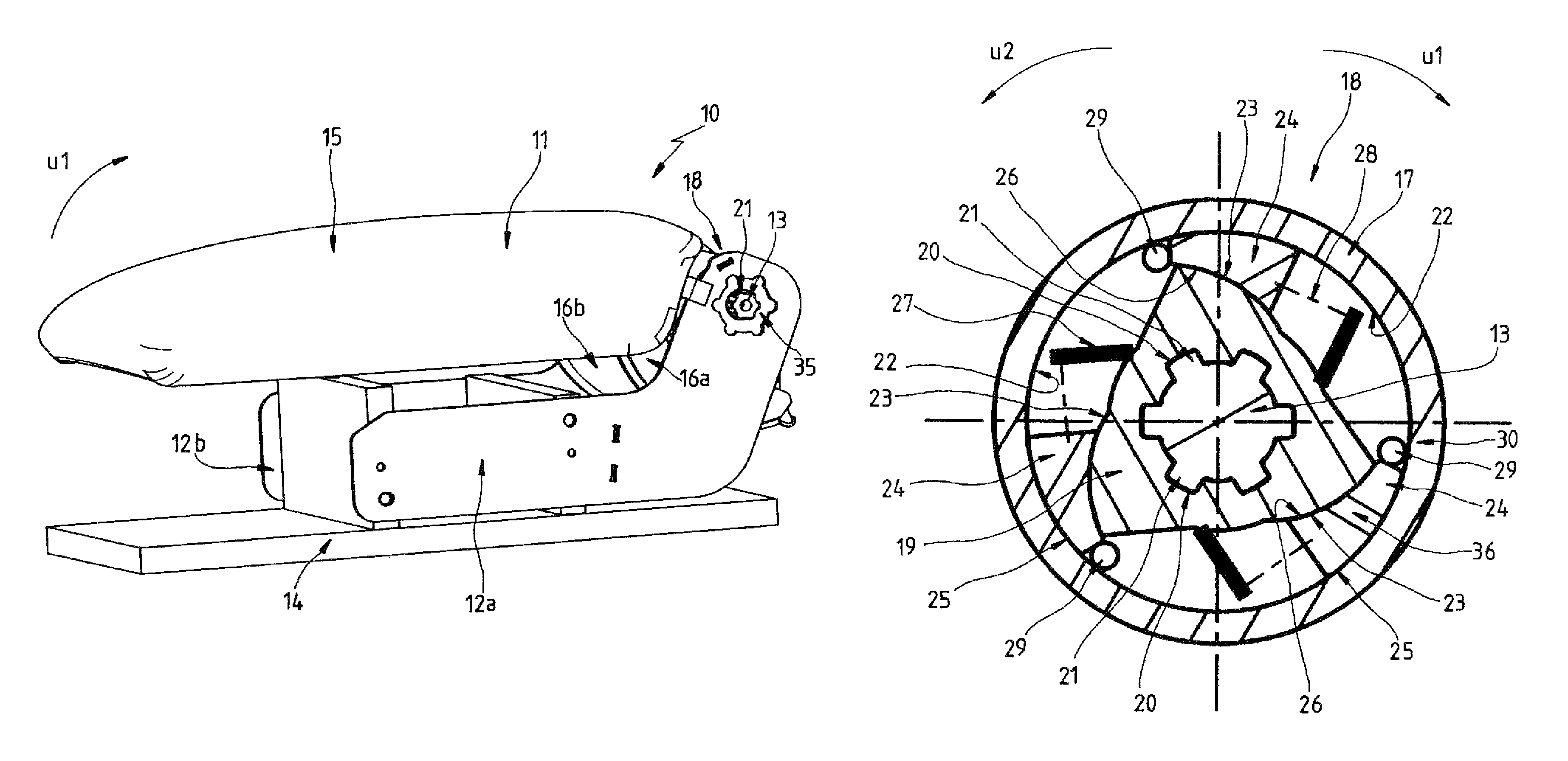
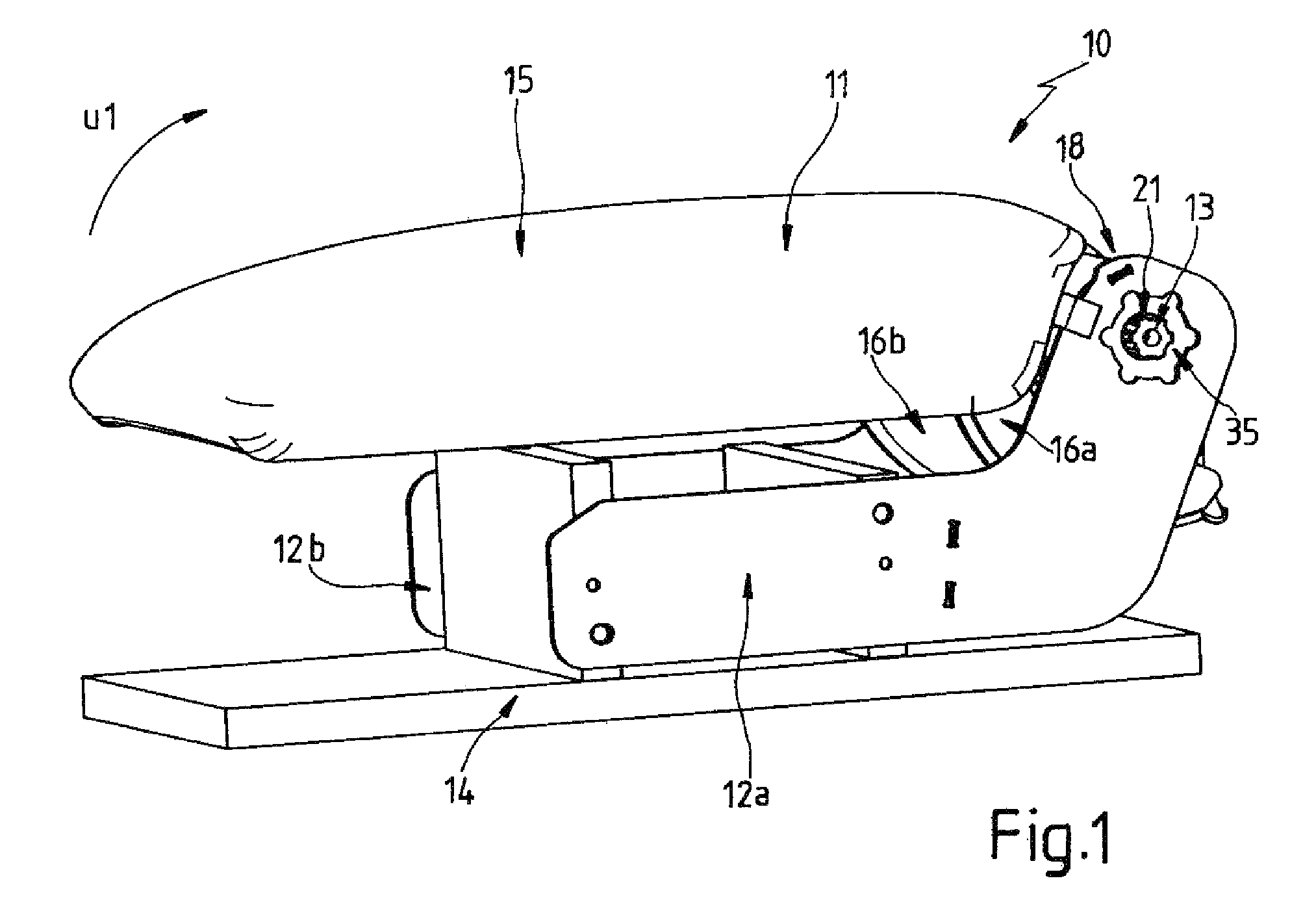
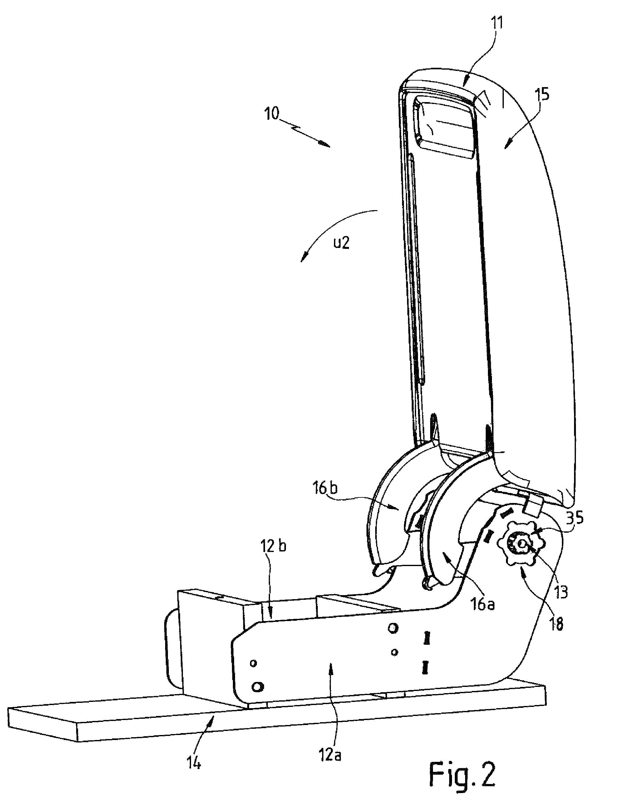
[0027]An armrest as a whole is designated in the figures at reference 10. Identical reference numerals in the different is figures also designate corresponding parts by the addition or omission of lower case letters.

[0028]The armrest comprises an armrest part 11. The armrest part 11 is provided with a pad 15. The armrest part 11 is pivotal about a pivot axle 13 or a geometric pivot axis s. The armrest part 11 can be moved from the use position illustrated in FIG. 1 in angular direction u1 into the out-of-use position illustrated in FIG. 2. The armrest part 11 can be moved from the out-of-use position illustrated in FIG. 2 in direction u2 to the use position illustrated in FIG. 1. The positions according to FIGS. 1 and 2 represent end positions of the armrest part 11.

[0029]The pivot axle 13 is connected solidly to base parts 12a and 12b forming a base element. The base parts 12a and 12b are fixed on a motor-vehicle frame member 14. The pivot axle 13 has splines 21 that engage positiv...


PUM


Abstract

A motor-vehicle armrest has a base fixed on the vehicle and defining an axis and an armrest part pivotal on the base about the axis and having a first concave surface turned radially inward toward a second convex surface of the base. A wedge-shaped sprag is slidable between the surfaces generally angularly of the axis between a locking position in which the armrest part is arrested relative to the base and a release position in which pivoting of the armrest part with respect to the base is possible. The sprag has a first contact face cooperating with the first surface of the armrest part and a second nonparallel contact face cooperating with the second surface of the base. The sprag is biased into the locking position and can be moved into the release position.

Description

CROSS-REFERENCE TO RELATED APPLICATIONS[0001]This application claims the priority of German patent application 10 2008 023 751.5-16 filed 15 May 2008.FIELD OF THE INVENTION[0002]The invention relates to an accessory for a motor-vehicle interior, in particular an armrest for a motor-vehicle seat, the accessory being pivotal on a base element fixed on the vehicle and comprising a freewheel with at least one sprag movable between a locking position in which the accessory is arrested relative to the base element and a release position in which pivoting of the accessory with respect to the base element is possible, the sprag being provided with a first contact face cooperating with a first counter-surface of the accessory and a second contact face with a second counter-surface of the base element.[0003]Such an accessory is known from DE 103 56 293. This document relates to a pivotal armrest. The pivot range of the armrest is divided into three parts. The armrest has a freewheel that enab...

Claims


Application Information

Patent Timeline
Patent Type & Authority Patents(United States)
IPC IPC(8): E05C19/00E05C3/04B60N2/75
CPCB60N2/4606B60N2/4633B60N2/4686B60N2/753B60N2/767B60N2/793Y10T292/42Y10T292/1085Y10T292/03
Inventor NUSS, RALPHHIMMELHUBER, ERWINZEITLER, DANIEL
Owner GRAMMER AG
Why Eureka
Try Eureka