Shank chisel

a shank chisel and chisel head technology, applied in the field of shank chisels, can solve the problems of inability to carry out safe and cramped conditions, wear along with the chisel head, and inability to replace the shank chisel, so as to facilitate the installation work, facilitate the installation, and facilitate the installation

Active Publication Date: 2013-10-08
BETEK BERGBAU UND HARTMETALLTECHN KARL HEINZ SIMON
View PDF15 Cites 8 Cited by
  • Summary
  • Abstract
  • Description
  • Claims
  • Application Information

AI Technical Summary

Benefits of technology

[0009]This construction ensures that an actuating element of a tool can be guided in the gap region. For the removal of a shank chisel, a tool extension is inserted into the tool fitting and a section of the actuating element adjoining the tool extension is guided through the gap region. The gap region makes it possible for the actuating element to be guided through the receiving bore when the tool extension is inserted into the tool fitting. It is thus possible to use the actuating element for both installing and removing the shank chisel through the receiving bore.
[0010]According to one embodiment of this invention, the gap region is formed between the circumference surface of the cylindrical chisel shank, which has a first diameter, and an end section of the shank extension, which has a second diameter, with the second diameter being smaller than the first diameter. The gap region is situated in the vicinity of the diameter offset. If in addition, the central longitudinal axes of the chisel shank and the end section are aligned with each other and the gap region is composed of the annular space produced between the first and second diameter, then the tool fitting is circumferentially accessible, which facilitates attaching the tool to the shank chisel.
[0011]The tool fitting can be composed of or include a circumferential groove that permits the shank chisel to be easily produced as a turned part.
[0013]To permit the tool to be inserted safely into the tool fitting of the shank chisel even in cramped conditions and blind locations, a shank chisel according to this invention can be embodied so that the chisel shank and / or the shank extension each is conveyed into the tool fitting via a chamfer.
[0014]To facilitate the installation work, it is possible to provide an embodiment in which a wear-protection disk is pulled onto the clamping sleeve and holds the clamping sleeve in a prestressed state. The wear-protection disk can be slid off from the clamping sleeve in the direction toward the chisel head. When it has been slid off, the wear-protection disk is situated in a transition section of the chisel shank, which is formed between the chisel head and the clamping sleeve, and releases the clamping sleeve. The clamping sleeve prestressed by the wear-protection disk can easily be installed using the tool according to this invention.

Problems solved by technology

When the tool is in use, a chisel tip secured to the chisel head is guided across the surface to be stripped and as a result, wears along with the chisel head.
With the known system, replacing a shank chisel is labor-intensive and cannot be carried out safely in cramped conditions.

Method used


Image

  • Shank chisel
  • Shank chisel
  • Shank chisel

Examples


Embodiment Construction

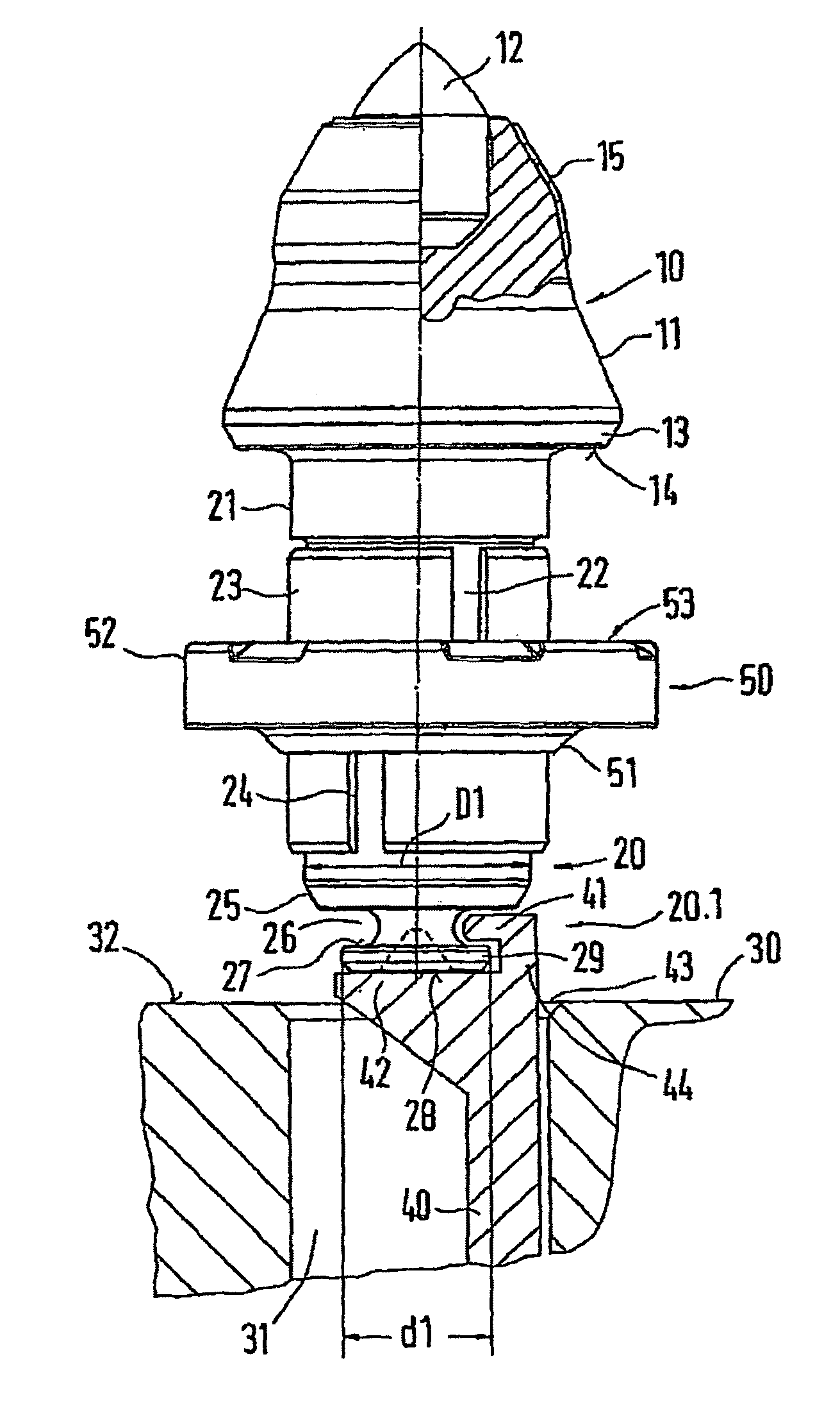
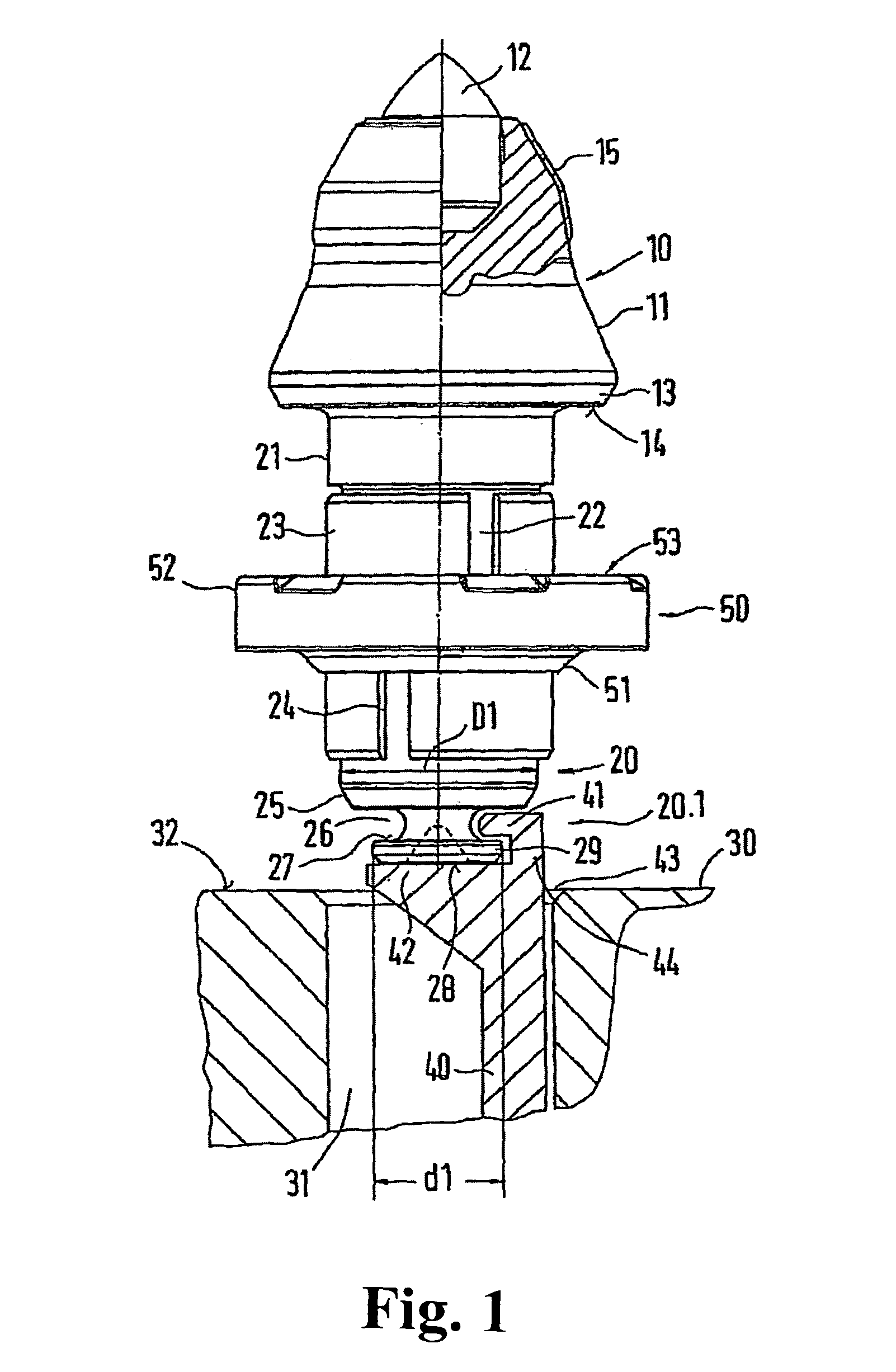
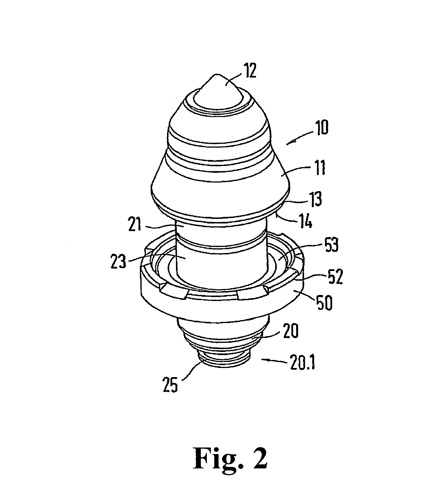
[0018]FIG. 1 shows a shank chisel with a chisel head 10 and a chisel shank 20. The chisel head 10 has a receptacle into which a chisel tip 12 is inserted and therein soldered in place. The chisel tip 12 can be comprised of hard metal. Adjoining the chisel tip 12, the chisel head 10 has lateral deflecting surfaces 11. When the tool is in use, stripped stone material flows past the recesses 16. In the region closer to the chisel tip 12, the deflecting surfaces 11 are covered with an armoring 15, which is embodied in the form of a welded coating. The chisel head 10 is thus protected in this particularly wear-prone region.

[0019]In the transition region of the chisel head 10 to the chisel shank 20, the chisel head 10 has a collar 13. The collar forms a downward-oriented support surface 14. A cylindrical transition section 21 adjoins the rotationally symmetrical collar 13. A holding section 22 also embodied as a cylinder is formed onto the transition section 21. At its free end, the holdi...


PUM

PropertyMeasurementUnit
diameteraaaaaaaaaa
circumferenceaaaaaaaaaa
spring-elasticaaaaaaaaaa

Abstract

A shank chisel including a chisel head and a chisel shank, wherein the chisel shank bears a clamping sleeve in which the chisel shank is held captively in a direction of a longitudinal axis and is freely rotatably about the longitudinal axis. To allow the shank chisel to be both assembled and disassembled through a chisel receptacle of a chisel holder that is formed as a receiving bore, according to this invention, the chisel shank bears at its end remote from the chisel head a shank extension, the shank extension has a tool receptacle, and the tool receptacle is accessible by way of a spacing region of the shank extension in the axial direction of the chisel that is set back from the lateral surface of the chisel shank and / or from the lateral surface of the clamping sleeve.

Description

BACKGROUND OF THE INVENTION[0001]1. Field of the Invention[0002]This invention relates to a shank chisel including a chisel head and a chisel shank. The chisel shank has a clamping sleeve in which the chisel shank is secured in captive fashion in a direction of a longitudinal axis and is able to rotate freely around its longitudinal axis.[0003]2. Discussion of Related Art[0004]Shank chisels of this kind are known. They are usually used in mining machines, road milling machines, and the like for stripping asphalt, rock, and the like. The shank chisels are mounted in chisel holders that are secured to a milling roller of the machine. The chisel holders have a bore acting as a chisel receptacle. The chisel shank is inserted with its clamping sleeve into the chisel receptacle. As a result, the clamping sleeve clamps against the inner wall of the chisel receptacle in a spring-elastic fashion. In the clamping sleeve, the shank chisel is secured in captive fashion in a direction of its lon...

Claims


Application Information

Patent Timeline
Patent Type & Authority Patents(United States)
IPC IPC(8): E21C35/197
CPCB28D1/188E21C35/197E21C2035/1826E21C35/188
Inventor WOHRSTEIN, THOMASLEHNERT, THOMAS
Owner BETEK BERGBAU UND HARTMETALLTECHN KARL HEINZ SIMON
Why Eureka
Try Eureka