Image forming apparatus

a technology of forming apparatus and forming tube, which is applied in the direction of printing mechanism, spacing mechanism, printing, etc., can solve the problems of affecting the flushing effect, so as to achieve smooth flushing

Active Publication Date: 2013-10-08
SEIKO EPSON CORP
View PDF3 Cites 0 Cited by
  • Summary
  • Abstract
  • Description
  • Claims
  • Application Information

AI Technical Summary

Benefits of technology

[0006]An advantage of some aspects of the invention is that it provides an image forming apparatus in which agitation of liquid is performed by reciprocation of a carriage while reducing a load on a carriage belt, a carriage guide, or the like.
[0009]In the image forming apparatus according to the above aspect of the invention, in a case where agitation of the liquid is required, the driving section which moves the carriage is controlled such that the operation areas of a plurality of places set within the movable range of the carriage are changed over and the carriage then reciprocates within the operation areas. In this way, it is possible to disperse a load on a carriage guide, a carriage belt, or the like, so that it is possible to perform agitation of liquid by reciprocation of the carriage while reducing the load on these.
[0011]Further, in the image forming apparatus according to the above aspect of the invention, the operation areas of a plurality of places may be set such that the reciprocating ranges of the carriage do not overlap each other. In this way, it is possible to more reliably disperse a load which acts on the carriage guide, the carriage belt, or the like.
[0013]Further, in the image forming apparatus according to the above aspect of the invention, as the operation areas of a plurality of places, a first operation area and a second operation area may be respectively set on one end side and the other end side of the movable range of the carriage, the second operation area may be an area which includes a flushing area that receives liquid discharged from the discharge head at the time of a flushing operation, and the agitation control section may be a section which selects the first operation area in the case of reciprocating the carriage without a flushing operation of the discharge head and selects the second operation area in the case of reciprocating the carriage with the flushing operation of the discharge head. In this way, it is possible to smoothly perform the flushing operation while agitating the liquid and also it is possible to disperse a load which acts on the carriage guide, the carriage belt, or the like.

Problems solved by technology

Since pigment ink is ink in which pigment particles are dispersed in a solvent, if it is neglected over a long period of time, the pigment particles settle, so that the concentration of pigment becomes non-uniform in an upper portion and a lower portion of the tank.
However, in some cases, there is concern that a load may be concentrated on the specific portion of the carriage belt or the carriage guide.
However, weight increases or an increase in size is caused.

Method used


Image

  • Image forming apparatus
  • Image forming apparatus
  • Image forming apparatus

Examples


Embodiment Construction

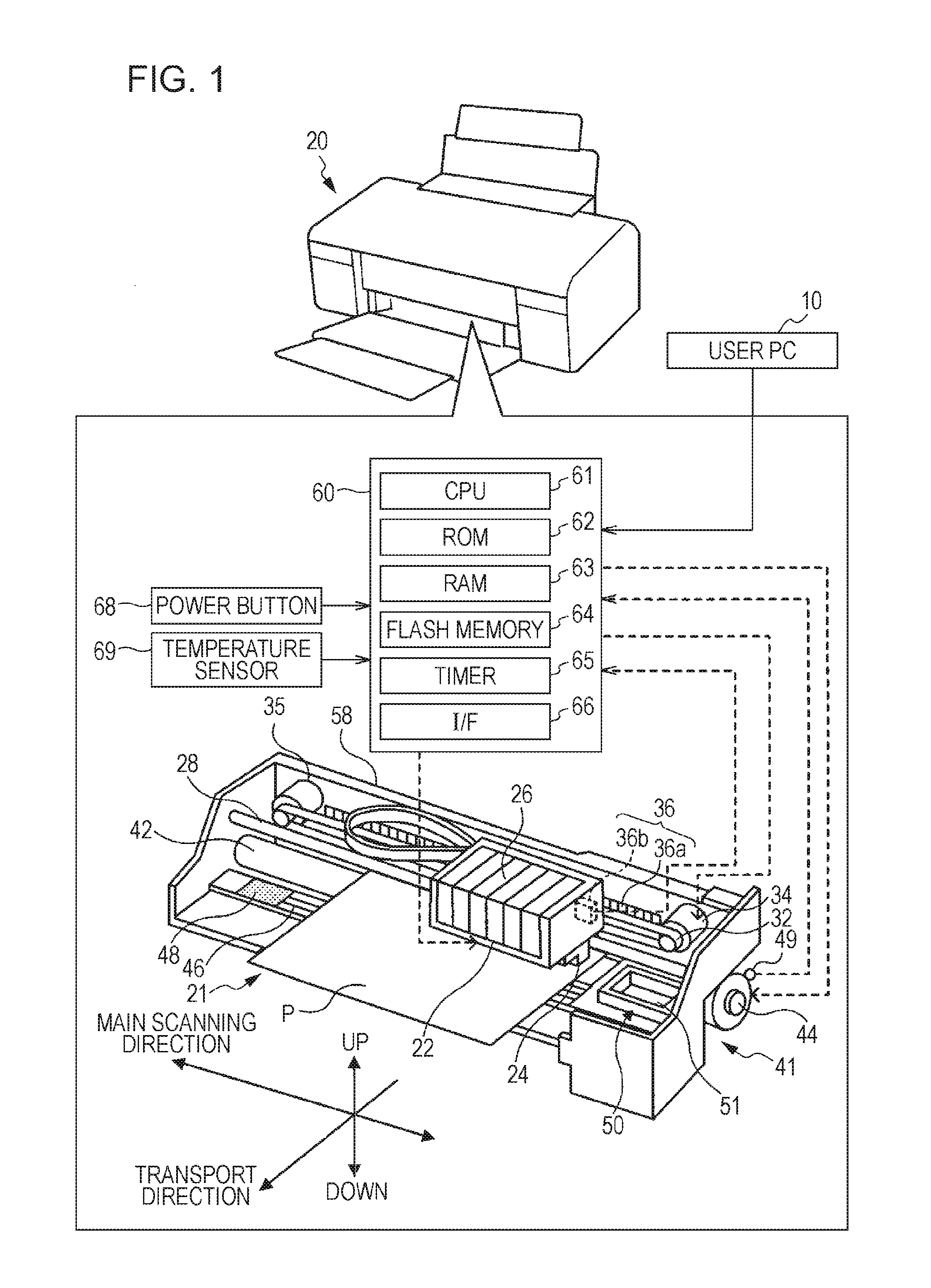
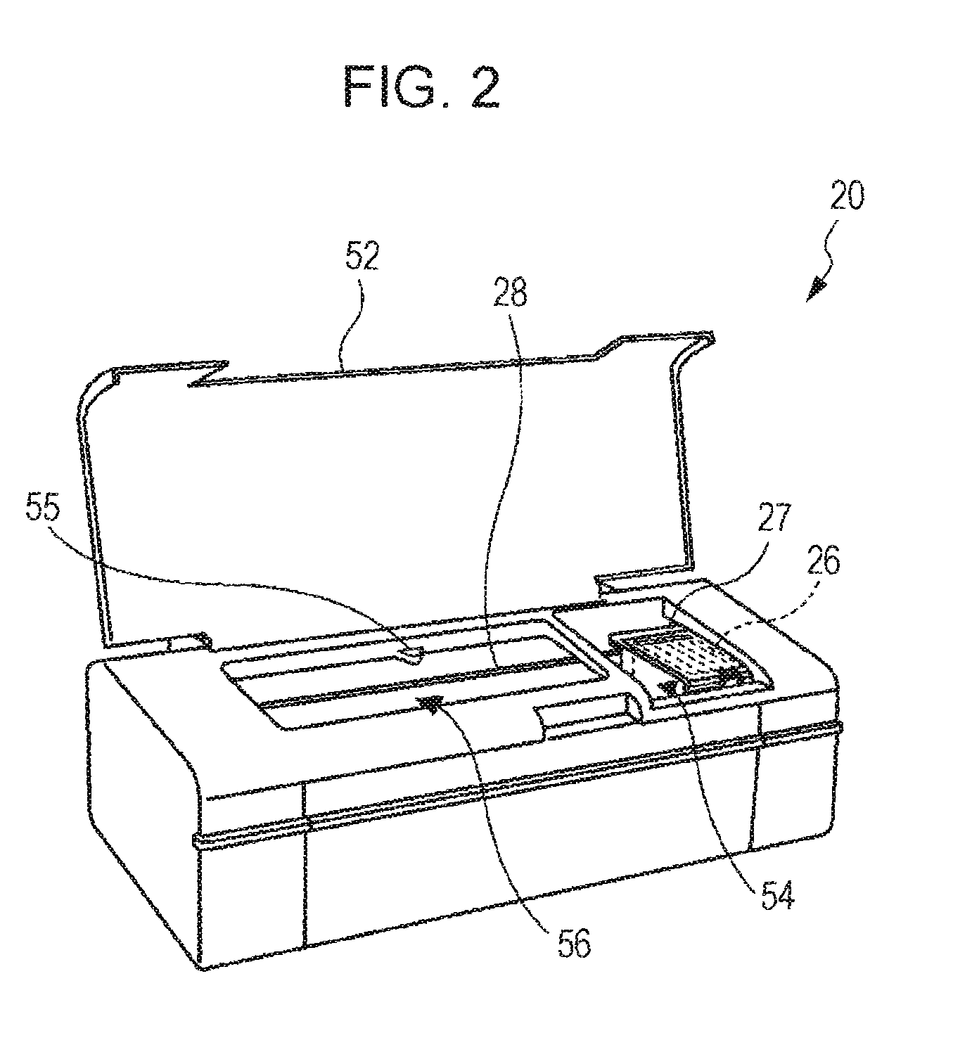
[0024]Next, embodiments of the invention will be described on the basis of the drawings. FIG. 1 is a configuration diagram illustrating the outline of the configuration of an ink jet printer 20 as one embodiment of the invention, and FIG. 2 is an exterior diagram illustrating the appearance of the ink jet printer 20 in a state where a printer cover 52 has been opened.

[0025]The ink jet printer 20 of this embodiment includes a paper feed mechanism 41 which transports paper P in a sub-scanning direction (a direction from the back to the front of the drawing), a printer mechanism 21 which performs printing by discharging ink droplets from nozzles formed in a printing head 24 with movement in a main scanning direction (a left-and-right direction in the drawing) with respect to the paper P transported onto a platen 46 by the paper feed mechanism 41, and a controller 60 which controls the whole apparatus, as shown in FIG. 1. At one end (the right end in FIG. 1) in the main scanning directi...


PUM


Abstract

An image forming apparatus that forms an image on a medium by discharging liquid from a discharge head, wherein a carriage on which the discharge head is mounted is made to be able to reciprocate, and in a case where agitation of liquid is required, control is performed such that operation areas of a plurality of places set within a movable range of the carriage are changed over and the carriage then reciprocates within the operation area.

Description

BACKGROUND[0001]1. Technical Field[0002]The present invention relates to an image forming apparatus which forms an image on a medium by discharging liquid from a discharge head.[0003]2. Related Art[0004]In the past, as this type of image forming apparatus, an image forming apparatus has been proposed in which the ink in the discharge head or a tank which is mounted on a carriage is agitated by reciprocating the carriage in a main scanning direction (refer to JP-A-2004-1411, for example). Since pigment ink is ink in which pigment particles are dispersed in a solvent, if it is neglected over a long period of time, the pigment particles settle, so that the concentration of pigment becomes non-uniform in an upper portion and a lower portion of the tank. For this reason, a configuration is made such that the concentration of ink can be uniformized by reciprocating (blank scan) the carriage in the main scanning direction without discharge of ink from a recording head.[0005]Usually, the ca...

Claims


Application Information

Patent Timeline
Patent Type & Authority Patents(United States)
IPC IPC(8): B41J23/00B41J2/195
CPCB41J2/16526B41J19/00B41J2/175
Inventor MURAHASHI, KENICHIYOSHIKAIE, KAZUYA
Owner SEIKO EPSON CORP
Why Eureka
Try Eureka