Liquid ejecting apparatus

a technology of liquid ejecting and ejecting parts, which is applied in the direction of printing, etc., can solve the problems of damage and increase the size of the print head unit, and achieve the effects of increasing the strength increasing the material and increasing the thickness of the connection end

Active Publication Date: 2013-10-08
CANON KK
View PDF5 Cites 3 Cited by
  • Summary
  • Abstract
  • Description
  • Claims
  • Application Information

AI Technical Summary

Benefits of technology

[0013]As a measure to prevent the aforementioned deformation of the connection end, a method has been considered wherein the strength of the connection end is increased by way of increasing the material thickness of the connection end or providing a plurality of beams that are parallel to the needle insertion direction at the space inside the print head unit. However, increasing the material thickness of the connection end, as well as increasing the number of beams, as mentioned above, causes a problem wherein the size of the print head unit increases, and as such is an inexpedient solution.
[0014]In light of the above problems, the present invention aims to provide a liquid ejection apparatus. The liquid ejection apparatus can increase the rigidity of a tank reception portion in accordance with the number of sub-ink-tanks, without an increase in the size of the liquid ejection apparatus.

Problems solved by technology

Because of this, the resultant force of each of the needle insertion forces that act on the connection end of the print head unit increases, and due to the resultant force of each of the insertion forces along the insertion direction of the needle, and insufficient strength of the connection end, there is a possibility that damage may occur, such as the connection end bending greatly, thus deforming and a crack forming therein.
However, increasing the material thickness of the connection end, as well as increasing the number of beams, as mentioned above, causes a problem wherein the size of the print head unit increases, and as such is an inexpedient solution.

Method used


Image

  • Liquid ejecting apparatus
  • Liquid ejecting apparatus
  • Liquid ejecting apparatus

Examples


Embodiment Construction

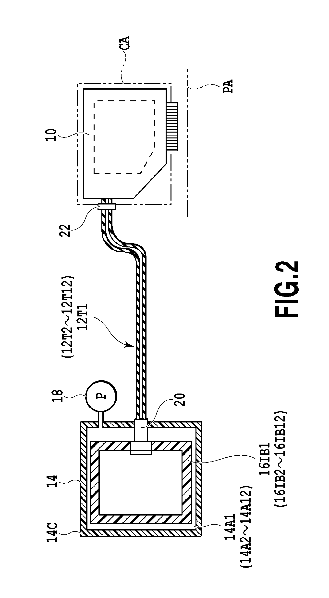
[0027]FIG. 2 is a configuration diagram that schematically illustrates a state where an example of the liquid ejection apparatus according to the present invention is connected to a main ink tank.

[0028]In FIG. 2 ink bags 16IB1 to 16IB12, which are respectively housed inside main ink tank 14, are detachably connected to the print head unit 10 through respective ink supply tubes 12T1 to 12T12 and respective tube connecting connectors 22 (only one ink bag, one ink supply tube and one connector are typically illustrated in FIG. 2). Sub-ink-tanks, to be described later, are mounted in a sub-ink-tank accommodation unit of the print head unit 10. Two colors of ink are mounted as a unit in one sub-ink tank. The main ink tank, having 12 differing ink colors, is connected to pressure regulating units of each of the sub ink tanks 26ST1 to 26ST6.

[0029]Although not shown in the figure, the main ink tanks 14 are disposed inside of an ink jet printer, for example. The main ink tank 14 has twelve s...


PUM


Abstract

In a liquid ejecting apparatus, sub-ink-tanks and a connection end of a sub-ink-tank accommodation unit are connected through a fixation portion and a connection pin. The sub-ink-tanks are fixed to a tank accommodation portion by way of small screws being respectively screwed, through through-holes and of the sub-ink-tanks, into threaded apertures.

Description

BACKGROUND OF THE INVENTION[0001]1. Field of the Invention[0002]The invention relates to a liquid ejecting apparatus that is provided with a tank accommodation unit for accommodating sub-ink-tanks that are connected to a main ink tank through ink tubes.[0003]2. Description of the Related Art[0004]There are cases where ink jet printers must deal with the printing of relatively large amounts of ink. For example, as shown in Japanese Patent Laid-Open No. 2002-307712, there are cases where sub-ink-tanks are provided on a print head unit that has an ink ejection portion that ejects ink, and main ink tanks, which supply ink to the sub-ink-tanks, are provided separately on the main body of the printer. The sub-ink-tanks of the print head unit and the main ink tanks are connected by ink supply tubes that form ink supply pathways. Herewith, each of the inks from ink retention units of each of the main ink tanks is separately supplied to the sub-ink-tanks through the set of ink supply tubes.[...

Claims


Application Information

Patent Timeline
Patent Type & Authority Patents(United States)
IPC IPC(8): B41J2/175B41J2/17
CPCB41J2/17509
Inventor IKEBE, NORIHIROUDAGAWA, KENTA
Owner CANON KK
Why Eureka
Try Eureka