Thermally conductive and electrically insulative polymer compositions containing a low thermally conductive filler and uses thereof

a technology of thermal insulation polymer and filler, which is applied in the direction of solid balls, semiconductor/solid-state device details, sport apparatus, etc., can solve the problems of high cost of ceramic filler, limited use of electrically conductive fillers in such applications, and limited number of ceramic filler types currently used for thermally conductive composites, etc., to achieve high thermal conductivity in polymer composites, high volume contents, and high thermal conductivity

Active Publication Date: 2013-10-08
SHPP GLOBAL TECH BV
View PDF85 Cites 23 Cited by
  • Summary
  • Abstract
  • Description
  • Claims
  • Application Information

AI Technical Summary

Benefits of technology

[0014]Additional advantages will be set forth in part in the description which follows, and in part will be obvious from the description, or can be learned by practice of the aspects described below. The advantages described below will be realized and attained by means of the elements and combinations particularly pointed out in the appended claims. It is to be understood that both the foregoing general description and the following detailed description are exemplary and explanatory only and are not restrictive.

Problems solved by technology

The use of electrically conductive fillers in such applications is limited to low volume contents, since electrical conductivity is achieved at significantly lower filler loadings than thermal conductivity.
The number of ceramic filler types that can currently be used for thermally conductive composites is relatively limited, since most ceramic fillers are thermally insulative or have a relatively low thermal conductivity.
Consequently, ceramic fillers with a high thermal conductivity are typically expensive to use and the design freedom to control other properties, such as mechanicals, flow and heat stability, is limited.

Method used


Image

  • Thermally conductive and electrically insulative polymer compositions containing a low thermally conductive filler and uses thereof
  • Thermally conductive and electrically insulative polymer compositions containing a low thermally conductive filler and uses thereof
  • Thermally conductive and electrically insulative polymer compositions containing a low thermally conductive filler and uses thereof

Examples


example 1

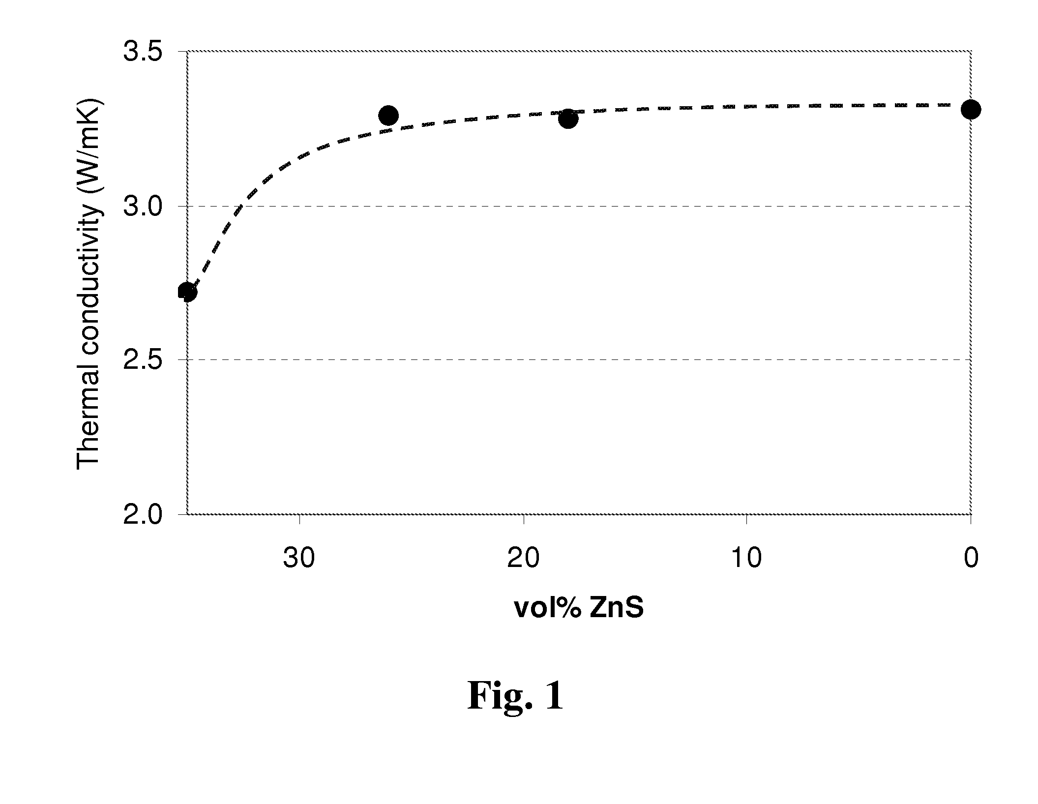
[0166]HDPE (Hostalen GC-7260, Basell), ZnS (Sachtolith (agglomerates of sub-μm particles), Sachtleben), BN (Coolflow CF300 (platelets / agglomerates, D50=15-25 μm), Momentive Performance Materials) and Graphite (Thermocarb TC300 (platelet with D90˜200 μm), Asbury Graphite) were formulated into a composition in the proportions set forth below in Table 1. The HDPE, ZnS, BN and Graphite were premixed in the solid state and were subsequently melt-compounded at 200° C. and 80 rpm on a Thermo Scientific Haake Polylab OS system equipped with a batch-mixer with Roller rotors, having a total internal volume of 65 cm3. The compositions were compression molded into 10×5×3 cm plaques by using a Dr Collin press at 240° C. and 100 bar. Cylindrical-shaped samples (3 mm thick, 12.7 mm diameter) were cut from the plaques and the through-plane thermal conductivity of the sample compositions was measured according to ASTM E1461. The results are set forth below in Table 1 and FIG. 1.

[0167]

TABLE 1VolumeZn...

example 3

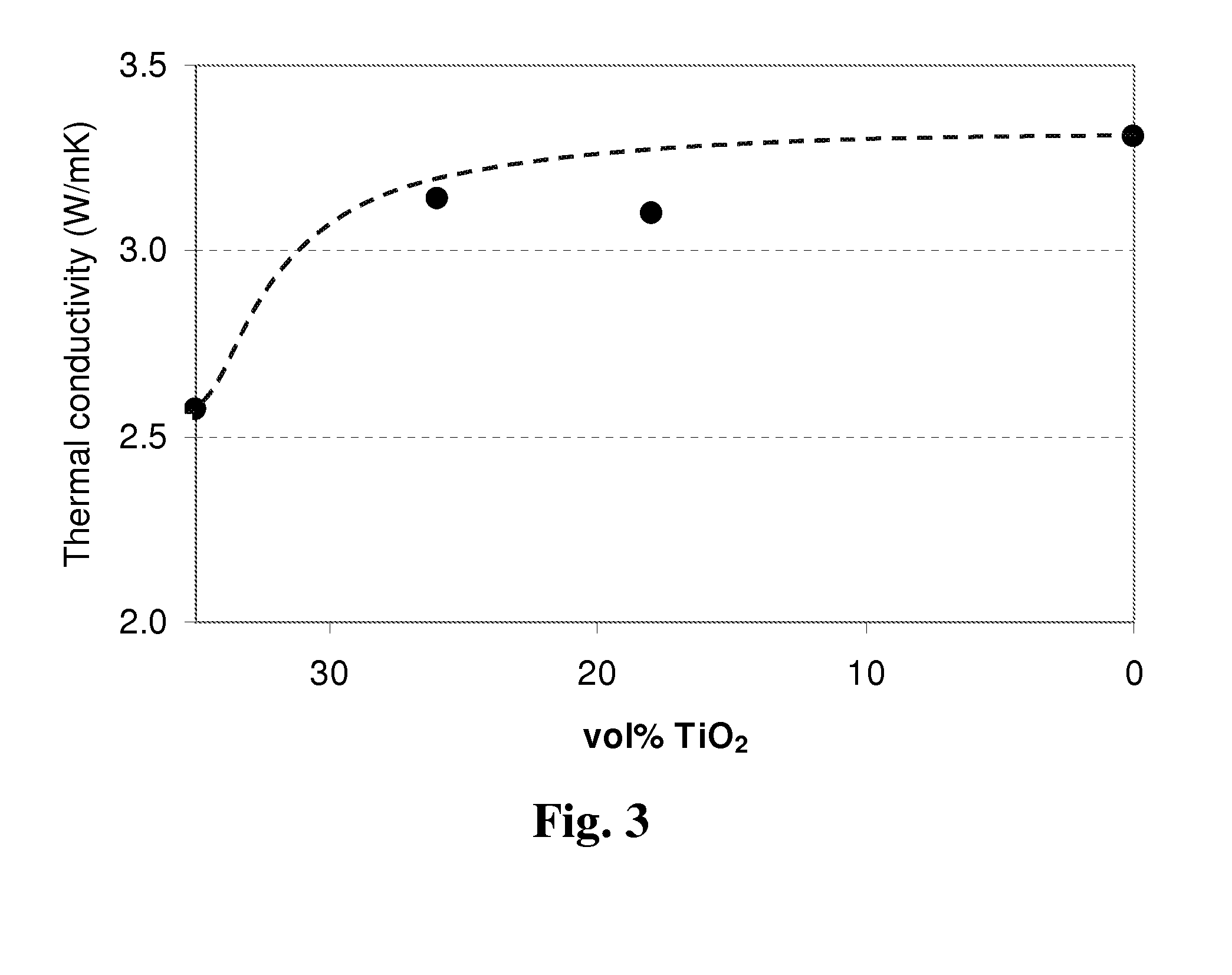
[0174]Similar to the process of Example 1, HDPE (Hostalen GC-7260, Basell), TiO2 (Tiona RL-91 (agglomerates of sub-μm particles), Millennium), BN (Coolflow CF300 (platelets / agglomerates, D50=15-25 μm), Momentive Performance Materials) and Graphite (Thermocarb TC300 (platelet with D90˜200 μm), Asbury Graphite) were formulated into a composition in the proportions set forth below in Table 3 and the through-plane thermal conductivity of the sample compositions was measured according to ASTM E1461. The results are set forth in Table 3 and FIG. 3.

[0175]

TABLE 3VolumeTiO2BNGraphiteTCResistivityRun #Polymer(vol %)(vol %)(vol %)(W / mK)(Ω· cm)9HDPE350152.57>10710HDPE269153.14>10711HDPE1818153.08>10712HDPE035153.31>107

[0176]Table 3 and FIG. 3 show the thermal conductivities of thermally conductive composites containing 15 vol % graphite and a total filler content of 50 vol %, where the TiO2 and BN volume contents vary. This means that the total volume content of filler is constant at 50 vol % a...

example 5

[0182]Similar to the process of Example 1, HDPE (Hostalen GC-7260, Basell), MgO (Maglite DE (agglomerates of sub-μm particles), Promecome), BN (Coolflow CF300 (platelets / agglomerates, D50=15-25 μm), Momentive Performance Materials) and Graphite (Thermocarb TC300 (platelet with D90˜200 μm), Asbury Graphite) were formulated into a composition in the proportions set forth below in Table 5 and the through-plane thermal conductivity of the sample compositions was measured according to ASTM E1461. The results are set forth in Table 5 and FIG. 5.

[0183]

TABLE 5VolumeMgOBNGraphiteTCResistivityRun #Polymer(vol %)(vol %)(vol %)(W / mK)(Ω· cm)17HDPE350152.64>10718HDPE269153.29>10719HDPE1818153.28>10720HDPE035153.31>107

[0184]Table 5 and FIG. 5 show the thermal conductivities of thermally conductive composites containing 15 vol % graphite and a total filler content of 50 vol %, where the MgO and BN volume contents vary. This means that the total volume content of filler is constant at 50 vol % and t...


PUM

PropertyMeasurementUnit
vol %aaaaaaaaaa
volume resistivityaaaaaaaaaa
thicknessaaaaaaaaaa

Abstract

Disclosed herein are compositions comprising a. from 35 to 80 vol % of a thermoplastic polymer; b. from 5 to 45 vol % of a low thermally conductive, electrically insulative filler with an intrinsic thermal conductivity of from 10 to 30 W / mK; c. from 5 to 15 vol % of a high thermally conductive, electrically insulative filler with an intrinsic thermal conductivity greater than or equal to 50 W / mK; and d. from 5 to 15 vol % of a high thermally conductive, electrically conductive filler with an intrinsic thermal conductivity greater than or equal to 50 W / mK, wherein the composition is characterized by: i. a thermal conductivity of at least 1.0 W / mK; and ii. a volume resistivity of at least 107 Ohm.cm. Also disclosed are articles and methods of use therefor.

Description

CROSS-REFERENCE TO RELATED APPLICATIONS[0001]This application claims the benefit of priority to U.S. Provisional Application No. 61 / 446,666, filed on Feb. 25, 2011, which is incorporated by reference herein in its entirety.BACKGROUND[0002]A need exists for polymer composites that are thermally conductive, yet electrically insulative. Polymers are electrical and thermal insulators, so thermally conductive fillers have to be added to provide thermal conductivity. High volume contents of filler are needed to achieve thermal conductivities suitable for efficient heat transport through a polymer composite. The use of electrically conductive fillers in such applications is limited to low volume contents, since electrical conductivity is achieved at significantly lower filler loadings than thermal conductivity. Therefore, typically so-called ceramic fillers with high thermal conductivities are added to these polymer compositions. The number of ceramic filler types that can currently be use...

Claims


Application Information

Patent Timeline
Patent Type & Authority Patents(United States)
IPC IPC(8): C08K3/06
CPCC08K3/0008H01B3/004H01L23/3737H01L2924/0002H01L2924/00C08K3/01C08L101/00C08L101/12C08K3/00H01B1/20H05K1/03C09K5/00C08J5/00
Inventor L'ABEE, ROYMERCX, FRANSVAN DER MEE, MARKKARLIK, DENNISGUO, MINGCHENGZOU, DAVID
Owner SHPP GLOBAL TECH BV
Why Eureka
Try Eureka