Air supply pipe and forced induction compressor

a technology of forced induction compressor and air supply pipe, which is applied in the direction of machines/engines, bends, combustion air/fuel-air treatment, etc., can solve the problem of limiting the piping space of air supply pipe to be compact, and achieve the effect of compact production

Inactive Publication Date: 2013-10-15
KOMATSU LTD
View PDF25 Cites 11 Cited by
  • Summary
  • Abstract
  • Description
  • Claims
  • Application Information

AI Technical Summary

Benefits of technology

[0008]According to the air supply pipe of the first aspect of the present invention, the cross-sectional shape of the curved pipe portion is a rectangular shape having longer sides in the third direction. Therefore, the air supply pipe can be compactly bent in the curved pipe portion compared to the case that the cross-sectional shape of the curved pipe portion is a circular shape. Accordingly, it is possible to compactly produce the piping space of the air supply pipe. Further, it is possible to enhance strength of the curved pipe portion compared to the case that the cross-sectional shape of the curved pipe portion is an elliptical shape or etc.
[0010]According to the air supply pipe of the second aspect of the present invention, it is possible to enhance flexibility in a bent condition of the curved pipe portion. Therefore, it is possible to compactly produce the piping space of the air supply pipe, and simultaneously, effectively avoid interference with the peripheral members.
[0012]According to the air supply pipe of the third aspect of the present invention, it is possible to inhibit the curved pipe portion from protruding towards peripheral members thereof, compared to the case that the outer edge of the rectangular pipe portion is bent. Therefore, the air supply pipe can be further compactly bent.
[0015]According to the air supply pipe of the fifth aspect of the present invention, it is possible to inhibit an air flow direction from being steeply bent within the curved pipe portion. Therefore, it is possible to reduce variation in speed of the air flowing out of the air supply pipe.
[0017]According to the present invention, it is possible to provide an air supply pipe whereby a piping space can be compactly produced and a forced induction compressor including the air supply pipe.

Problems solved by technology

JP-A-2006-240431 is uniformly formed in a cylindrical shape, and therefore, a bent portion of the air supply pipe is protruded towards peripheral members thereof Therefore, there is a limit to compactly produce the piping space for the air supply pipe.

Method used


Image

  • Air supply pipe and forced induction compressor
  • Air supply pipe and forced induction compressor
  • Air supply pipe and forced induction compressor

Examples


Embodiment Construction

Structure of Turbocharger 10

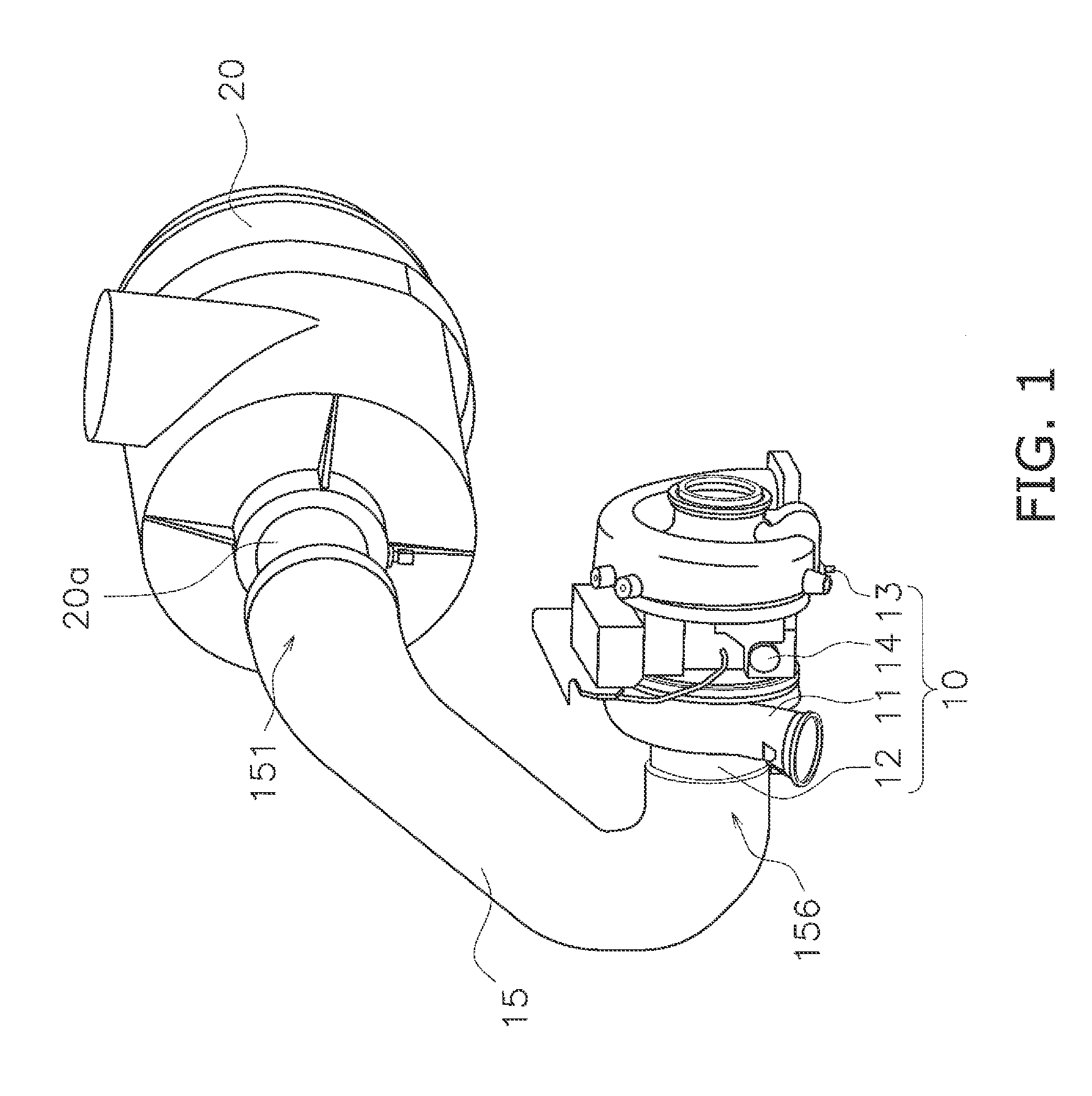
[0028]A structure of a turbocharger 10 according to an exemplary embodiment will be explained with reference to figures. FIG. 1 is a perspective view of the structure of the turbocharger 10 according to the exemplary embodiment. It should be noted that FIG. 1 illustrates a state that the turbocharger 10 is coupled to an air cleaner 20 through an air supply pipe 15.

[0029]The turbocharger 10 includes a compressor housing 11, an intake pipe 12, a turbine housing 13 and a center housing 14.

[0030]The compressor housing 11 accommodates a compressor impeller (not illustrated in the figures). The intake pipe 12 is coupled to the compressor housing 11. The intake pipe 12 transfers air flowing therein from the air supply pipe 15 to the compressor impeller. The turbine housing 13 accommodates a turbine wheel (not illustrated in the figures). The center housing 14 is disposed between the compressor housing 11 and the turbine housing 13 and accommodates a shaft coupli...


PUM


Abstract

An air supply pipe includes a curved pipe portion having a first end and a second end, a first straight pipe portion extended along a first direction and a second straight pipe portion extended along a second direction. The cross-sectional shape of the curved pipe portion is a rectangular shape having longer sides in a third direction.

Description

CROSS-REFERENCE TO RELATED APPLICATIONS[0001]This application claims priority to Japanese Patent Application No. 2011-011440 filed on Jan. 21, 2011, the disclosure of which is hereby incorporated herein by reference in its entirety.TECHNICAL FIELD[0002]The present invention relates to an air supply pipe and a forced induction compressor including an air supply pipe.BACKGROUND ART[0003]A method of bending an air supply pipe has been widely used so far for preventing the air supply pipe from interfering with peripheral members thereof when the air supply pipe is installed in a small space such as an engine compartment.[0004]In Japan Laid-open Patent Application Publication No. JP-A-2006-240431, for instance, an air supply pipe communicated with an air cleaner and a forced induction compressor is bent in a position closer to the forced induction compressor within an engine compartment of a construction machine. Accordingly, the air supply pipe is inhibited from interfering with periphe...

Claims


Application Information

Patent Timeline
Patent Type & Authority Patents(United States)
IPC IPC(8): F02M35/10F02B37/00
CPCF17D1/08F16L9/006F16L43/00F02M35/10111F02M35/10144F02M35/10157F02B37/00Y02T10/144Y10T137/85978Y02T10/12
Inventor NAKAE, YOSHIHIDENAKATA, KAZUSHI
Owner KOMATSU LTD
Why Eureka
Try Eureka