Engine with stub shaft supported cam gear and machine using same

Active Publication Date: 2013-10-15
CATERPILLAR INC
View PDF24 Cites 8 Cited by
  • Summary
  • Abstract
  • Description
  • Claims
  • Application Information

AI Technical Summary

Problems solved by technology

Spatial constraints in and around an engine make it problematic to arrange a gear train to properly distribute power from a crank shaft to the various pumps (e.g. lubrication pump, power take off pumps, fuel system pumps, etc.) and cam shaft that are necessary for proper operation of the engine and machine, while avoiding stress concentrations that could shorten engine life.

Method used


Image

  • Engine with stub shaft supported cam gear and machine using same
  • Engine with stub shaft supported cam gear and machine using same
  • Engine with stub shaft supported cam gear and machine using same

Examples


Embodiment Construction

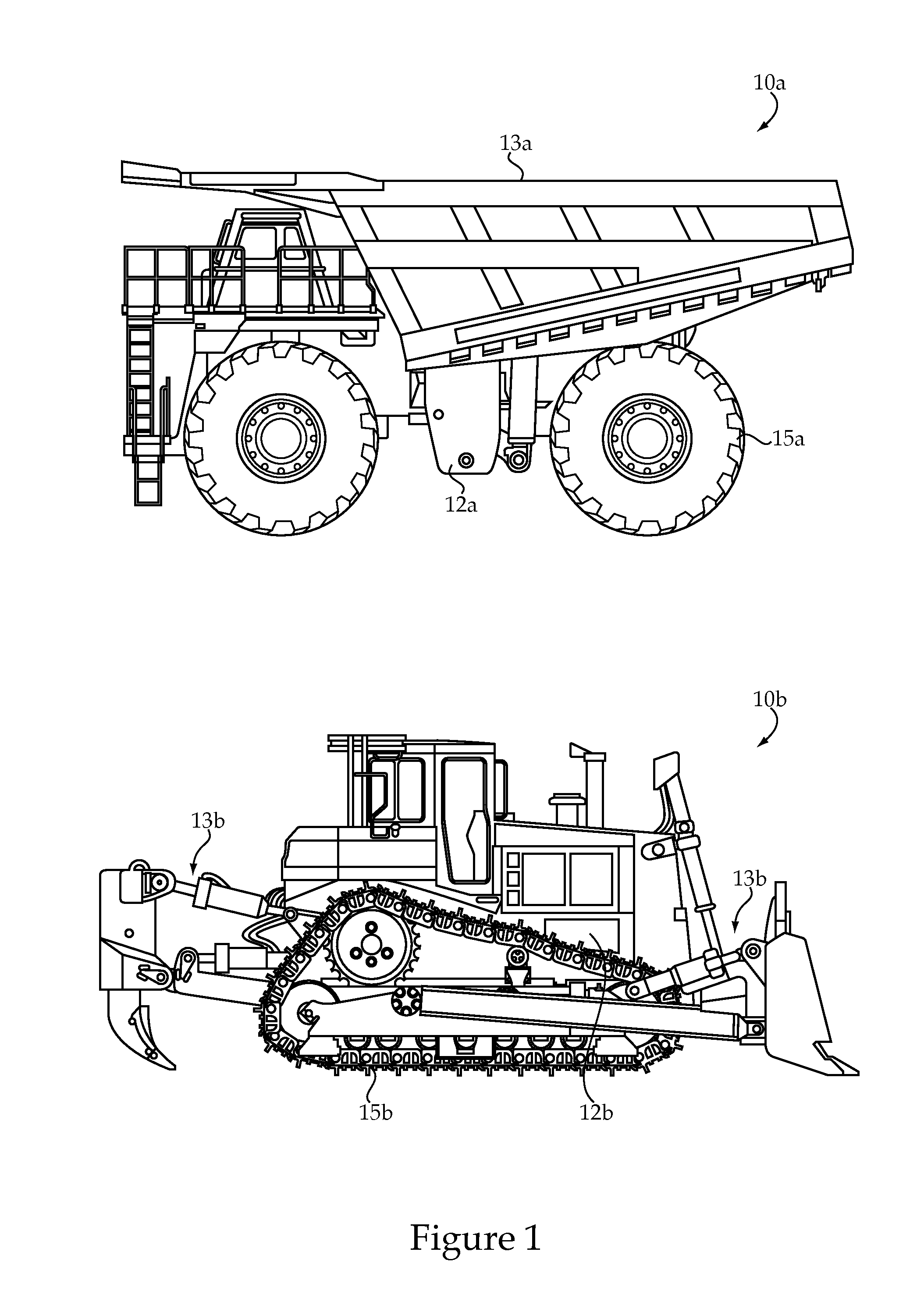
[0012]Referring to FIGS. 1 and 2, a machine according to the present disclosure might be a relatively large mining truck 10a or a large track type tractor 10b, either which may be powered by a relatively large compression ignition engine 14. Machines 10 according to the present disclosure may be characterized by a machine body 12 that supports the engine 14, which powers a conveyance 15 (e.g. wheels, tracks, or propeller etc.) and a hydraulically powered implement(s). In the case of mining truck 10a, the implement might be a dump bed 13a that is lifted to a dumping position by one or more hydraulic cylinders that receive pressurized hydraulic fluid from a pump driven by engine 14. In the case of track type tractor 10b, the implements include a ripper and blade 13b that each include a pair of hydraulic cylinders that receive pressurized hydraulic fluid from a pump powered by the engine 14.

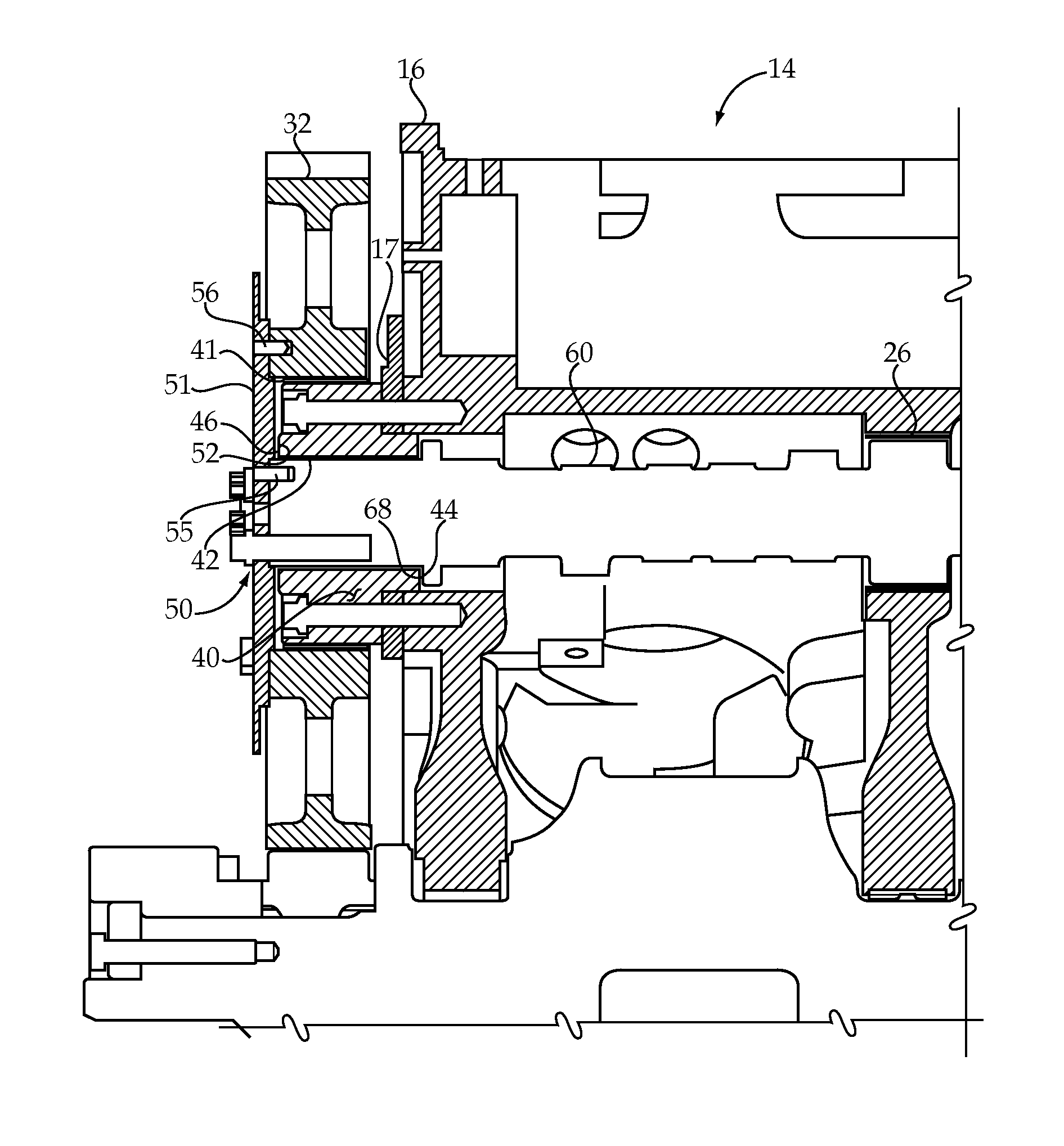
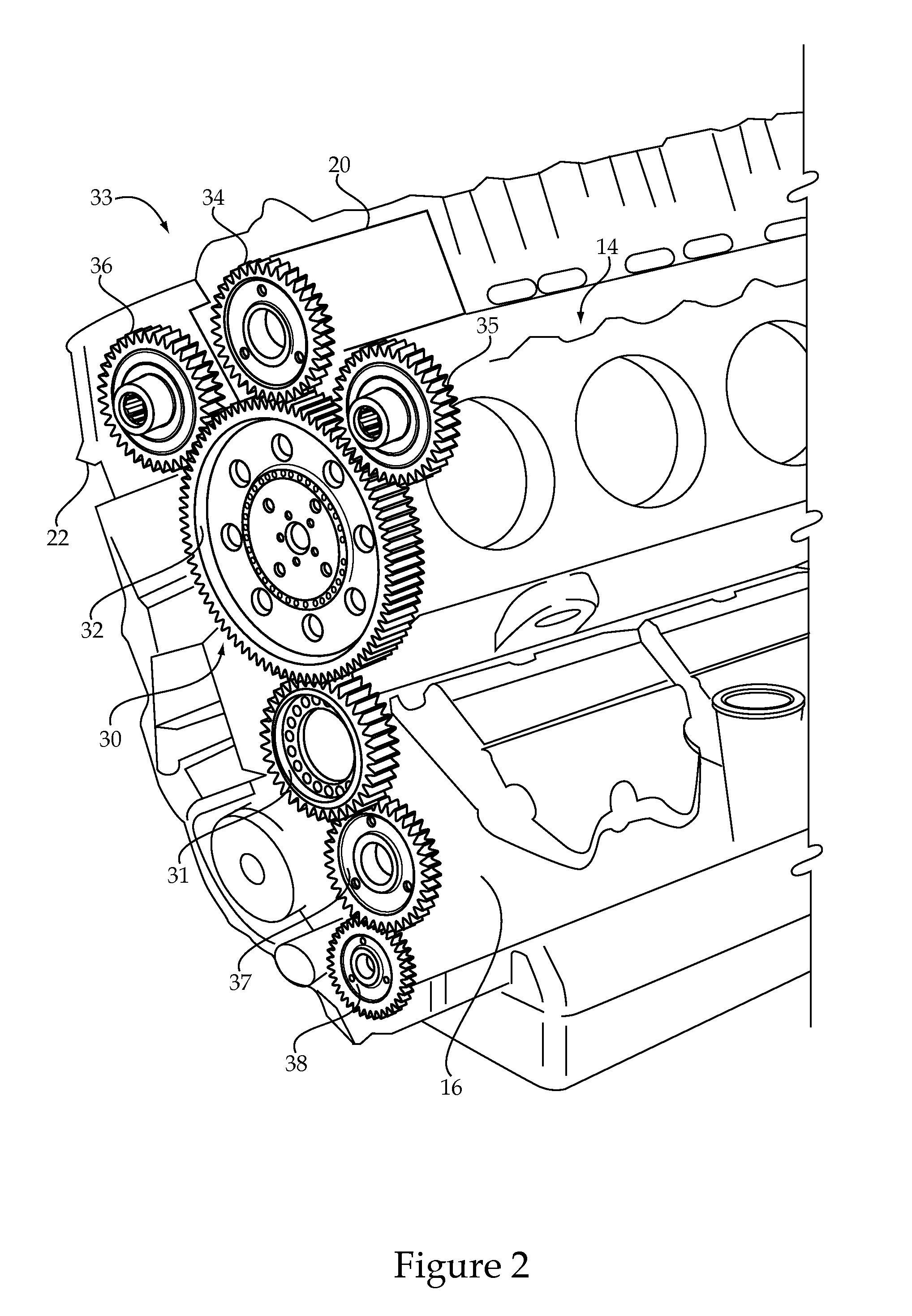
[0013]Referring specifically to FIG. 2, compression ignition engine 14 may include a housing 16 ...


PUM


Abstract

In one aspect, a machine includes an engine supported on a machine body. The engine includes a housing and a gear train that includes a crank gear meshed with a cam gear that is meshed with at least one powered gear. The cam gear is attached to a cam shaft by a drive coupler. The cam shaft is rotationally supported in the housing on a plurality of bearings, and the cam gear is rotationally supported on a stub shaft with an inner surface that is out of contact with the cam shaft. The stub shaft is attached to the housing of the engine.

Description

TECHNICAL FIELD[0001]The present disclosure relates generally to engine gear trains, and more particularly to a directly driven cam gear that drives rotation of a cam shaft and at least one powered gear.BACKGROUND[0002]In some engine applications, the engine is required not only to provide power to a conveyance to move the machine, but also to other systems of the machine. For instance, in large track type tractors and mining trucks, the engine powers hydraulic pumps to operate implements (ripper, blade) of a tractor or a dump cylinder for moving the dump bed of a mining truck. While there are many ways to configure an engine to provide power to hydraulic pumps, all gears of the gear train and all rotating shafts (e.g. crank shaft, cam shaft) must be adequately rotationally supported in order to avoid unacceptable stress concentrations and / or premature failure of one or more engine components. Spatial constraints in and around an engine make it problematic to arrange a gear train to...

Claims


Application Information

Patent Timeline
Patent Type & Authority Patents(United States)
IPC IPC(8): F01L1/02
CPCB60K25/02F01L1/026F02B67/04
Inventor PETRY-JOHNSON, TRAVIS THOMASMILLWARD, PHILIP CHRISTOPHERHEINBUCH, RYAN MICHAEL
Owner CATERPILLAR INC
Why Eureka
Try Eureka