Endoscopic bite block

a technology of endoscopic and bite block, which is applied in the field of bite block, can solve the problems of difficult for the subject to eject the bite block from the mouth, the upper gastro-intestinal endoscopic procedure itself, and the use of the bite block, and achieve the effect of effectively sampling the patient's breath and relieving discomfor

Active Publication Date: 2013-10-15
ORIDION MEDICAL 1987
View PDF24 Cites 12 Cited by
  • Summary
  • Abstract
  • Description
  • Claims
  • Application Information

AI Technical Summary

Benefits of technology

[0023]Furthermore, according to another preferred embodiment of the present invention, the front plate at the outer end of the bite block, which should lodge firmly against the lips of the subject, is preferably shaped such that it is not set at a uniform distance at the outer end of the tubular body, but rather, the top region is set further out than the bottom section, such that the natural position of the subject's upper lip region, projecting further out from his or her face than the lower lip region, does not prevent the front plate of the bite block from sitting firmly against both sets of lips. Such positioning of the front plate firmly against the whole of the subject's mouth also assists in overcoming any tendency for the bite block to tilt out of the subject's mouth because of moments generated should the subject move his teeth from the optimal natural gripping position.
[0026]Furthermore, according to yet another preferred embodiment of the present invention, the cross sectional area of the bite block inner channel is substantially closed off near its outer end by means of a flexible curtain, which maintains a generally closed inner volume for the central channel of the bite block. The flexible curtain has flaps such that it opens partially when the endoscope is inserted, and even enables the physician to maneuver the endoscope around while feeding it into the patient's esophagus, but still maintains a largely closed oral cavity volume. A small hole is preferably provided in this flexible curtain so that the subject's oral breathing can continue, largely through this hole. The closed oral cavity volume prevents excess mixing of the exhaled breath stream with air from outside the mouth, such that capnographic sampling can be accurately performed on undiluted breath as it is exhaled. Furthermore, the hole in the flexible curtain is preferably located close to the sampling opening in the roof of the bite block, such that the capnographic measurement is performed on an accurately representative sample of the exhaled and inhaled breath stream. In the capnographic bite block according to this preferred embodiment, the operation of the small hole and the sampling opening disposed close to it can be readily understood by considering these elements to be comparable to the effect of normal oral breath sampling without the use of a bite block. In this situation, the breath passing in and out of the large oral cavity, is sampled by the oral prong as it passes in a stream through the small opening of the subject's lips—at least in comparison to the cross sectional area of the mouth. Likewise with the capnographic bite block of the present invention, the breath passing in and out of the large combined internal volume of the oral cavity and the bite block is sampled by the sampling opening as it passes in a stream through the small hole in the flexible curtain. The bite block thus enables more efficient and accurate capnographic sampling than with prior art bite blocks under conditions of wide-open mouth breathing, which is common in endoscopic procedures.
[0027]Additional advantages of bite blocks according to the various preferred embodiments of the present invention, arise as a result of their correct and stable positioning within the mouth of the subject. When the bite block has an incorporated breath sampling cannula or a gas delivery system, or both, then the stability of the positioning of the bite block of the present invention in the user's mouth ensures that the desired breath sampling point or points, or the desired gas delivery point or points, are maintained during the procedure, and the tendency for the subject to push out or move the bite block, which would misplace the sampling or delivery ports, is significantly reduced in comparison with prior art bite blocks. Additionally, when a separate oral / nasal cannula is used, the firm placement of the subject's lips against the front plate of the bite block of the present invention assists in keeping the oral prong in its correct location sandwiched between the front plate and the subject's upper lip.

Problems solved by technology

The upper gastro-intestinal endoscopic procedure itself, together with the use of a bite block, is often highly uncomfortable for the subject.
Despite this, it is common for the subject to show opposition to the procedure.
The subject will also often oppose the placement of the bite block itself before the procedure, and more commonly during the procedure because of involuntary muscular reactions, by trying to manipulate it out of his or her mouth by means of the tongue or teeth.
The additional features are generally directed to assisting the physician in performing the endoscopic procedure with minimum interference from the subject, by making it more difficult for the subject to oppose the bite block, which generally means making it more difficult for the subject to eject the bite block from the mouth.
The bite block may thus be uncomfortable for the subject and may produce a feeling of being gagged even before the insertion of the endoscope itself.
Furthermore, large amounts of saliva are commonly produced during these procedures, and since one method of dealing with saliva is by manipulating it with the tongue, depressing the movement of the tongue may prevent the subject from dealing with it, again causing the subject to have a choking feeling.
In addition to the problems associated with the comfort and ease of use of prior art endoscopic bite blocks, a further problem exists when such prior art bite blocks are used together with breath sampling means, in particular capnographic sampling, or gas delivery, such as oxygen.
It is well known that a sedated subject is vulnerable to episodes of hypo-ventilation and apnea.
However, when subjects receive supplemental oxygen, as is recommended during sedation where breathing may be suppressed, apnea-induced oxygen de-saturation would be delayed until hyper-capnia ensued.
Concomitant use of prior art bite blocks and cannulae is often not an optimal solution, and the capnographic performance may be noticeably affected.
The alternative use of a nasal sampling cannula, in an attempt to overcome this problem, is generally inadequate, since it is known that during upper gastro-intestinal endoscopic procedures, it is usual for the subject to perform largely oral breathing alone, and the effectiveness of the nasal sampling is much reduced.
However, if oral / nasal sampling is performed in an attempt to overcome this problem, even if the oral sampling opening is placed in such a position so as not to interfere with the region required for the insertion and maneuvering of the Endoscope, the existence of majority oral exhalation still leads to another problem when using prior art devices.
When the subject's mouth is wide open, as it is during upper G-I endoscopy, the excess breath pressure within the oral cavity is very small, and the exhaled breath therefore becomes diluted with the inhaled air, and sampling is thus inaccurate.
Unlike the situation with carbon dioxide sampling, the use of a single device that integrates the bite block with oxygen delivery is mainly important for convenience, and is not mandated for providing optimal performance.
One possible disadvantage of the integrated device described in U.S. Pat. No. 5,273,032 is that the oxygen is delivered via two tunnels with ends that do not reach the nasal cavities, but instead direct the oxygen gas stream towards the nasal cavities.
Any tilt of the bite block inevitably causes a tilt in the direction of the nasal tunnels and consequently misdirects the oxygen gas stream away from the subject's nostrils.
However, even with this device, tilting of the bite block causes the prongs to be tilted also, and may consequently cause them to exit the nostrils.

Method used


Image

  • Endoscopic bite block
  • Endoscopic bite block
  • Endoscopic bite block

Examples


Embodiment Construction

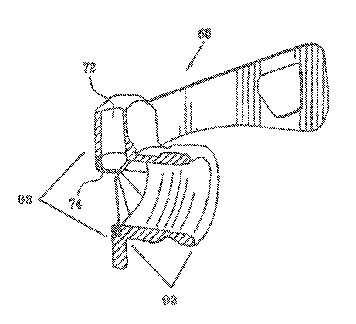
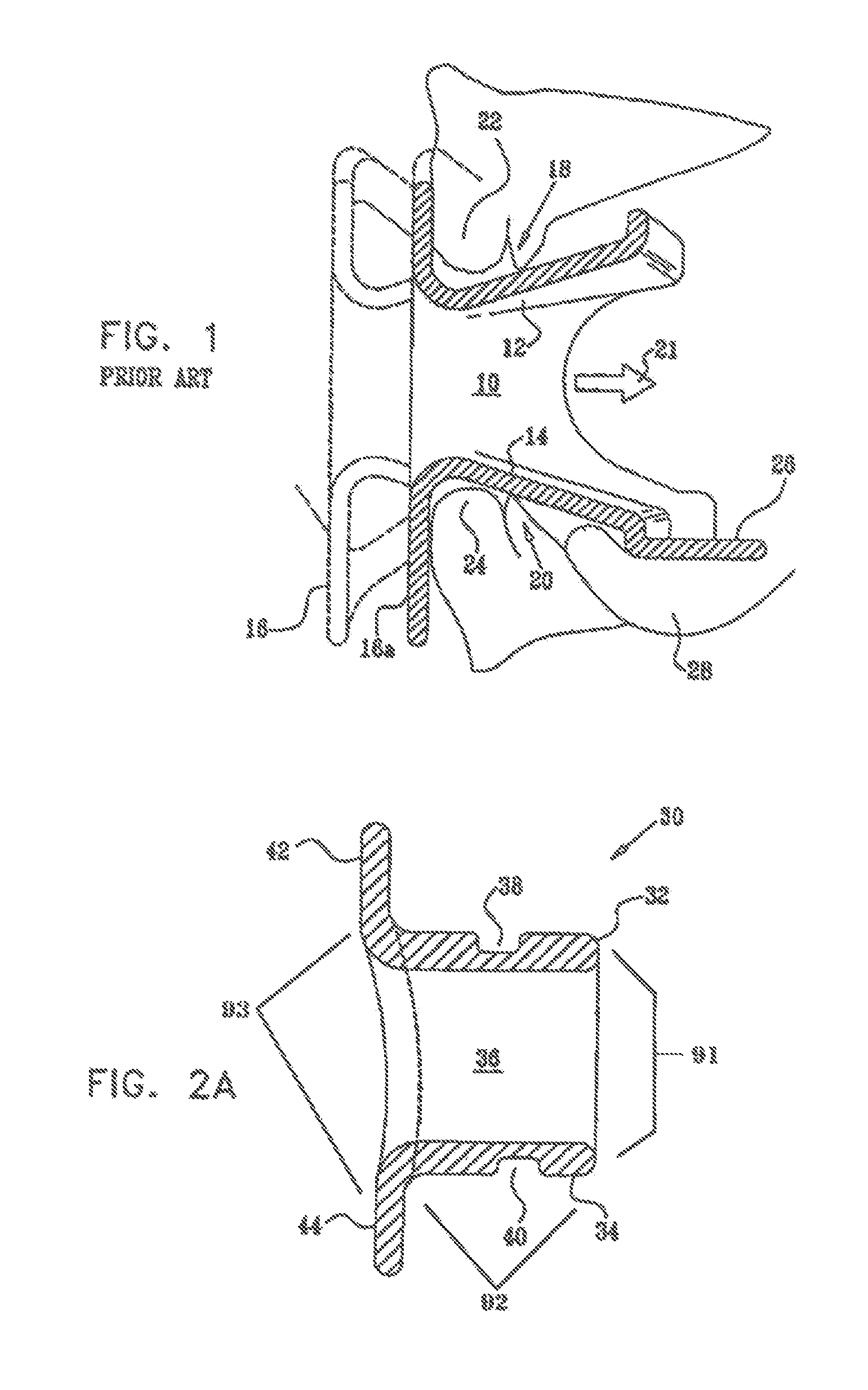
[0052]Reference is now made to FIG. 1, which illustrates schematically a prior art endoscopic bite block, such as that described in the above-mentioned U.S. Pat. No. 5,174,284. The bite block has an internal channel 10, with upper surface 12 and lower surface 14 inclined towards the front of the bite block, where the front plate 16 is connected. As the subject's teeth 18, 20, close, the bite block is pulled into the mouth in the direction 21 by the action of the teeth on the inclined upper 12 and lower 14 surfaces, so that the front plate moves from its initial position 16, until it is lodged firmly up against the subject's lips 22, 24, in position 16a. At the same time, the tongue depressor 26 firmly grips the subject's tongue 28, preventing it from moving.

[0053]However, the structure of the human mouth is such that the teeth positions are unlike those shown in the prior art drawing of FIG. 1, in that the upper and lower teeth do not close naturally onto each other, as shown in FIG...


PUM


Abstract

An endoscopic bite block, with teeth position defining regions which guide the subject's teeth to grip the bite block in their natural position, with the teeth of the upper jaw positioned further out than the lower jaw teeth. These teeth position defining regions are also preferably curved to match the curved shape of the jaw. The upper and lower parts of the front plate of the bite block may also be positioned at different distances out, so that upper and lower lip regions both contact the front plate snuggly. The bite block may be used with separate oral / nasal cannulae, or may incorporate breath sampling or gas supply cannulae. A flexible flapped curtain at the outer end of the bite block may be provided to largely enclose the inner volume of the bite block to enable more accurate capnographic sampling under conditions of wide-open mouth breathing.

Description

CROSS-REFERENCE[0001]The present application is a U.S. National Phase of PCT Application No. PCT / IL04 / 000430, filed May 20, 2004, which claims the benefit under 35 U.S.C. 119(e) of U.S. Provisional Application No. 60 / 472,368, filed May 20, 2003, the entire disclosures of both of which are incorporated herein by reference.FIELD OF THE INVENTION[0002]The present invention relates to the field of bite blocks for endoscopic use, adapted to provide for optimum subject comfort and tolerance, and especially such endoscopic bite blocks with incorporated gas sampling or delivery cannulae or for use with separate cannulae.BACKGROUND OF THE INVENTION[0003]A bite block is a device commonly used during upper gastro-intestinal endoscopic procedures to facilitate passage of an esophago-gastro-duodenoscopy (EGD) endoscope. The purpose of the bite block is to allow the physician to perform the procedure without the subject interfering by biting and damaging the endoscope tubing inserted via his mout...

Claims


Application Information

Patent Timeline
Patent Type & Authority Patents(United States)
IPC IPC(8): A61M16/00A62B9/06A61B19/00A61M16/04A61M16/06
CPCA61B1/00154A61M16/0488A61M16/0666A61B1/273A61B5/097A61C5/14A61B1/015A61B1/24A61M16/0493A61B2019/204A61B90/16A61M2230/43A61M2230/432A61M16/0841A61M16/085A61M16/0495
Inventor COLMAN, JOSHUA LEWISLEVITSKY, GERSHONPORAT, RON
Owner ORIDION MEDICAL 1987
Why Eureka
Try Eureka