Spring loaded compliant seal for high temperature use

a high temperature, seal technology, applied in the direction of machines/engines, mechanical equipment, lighting and heating apparatus, etc., can solve the problems of prior art seals that are too rigid and inflexible in order, and the inlet temperature of the turbine is limited to the material properties of the turbine,

Inactive Publication Date: 2013-10-15
FLORIDA TURBINE TECH
View PDF15 Cites 28 Cited by
  • Summary
  • Abstract
  • Description
  • Claims
  • Application Information

AI Technical Summary

Benefits of technology

[0016]FIG. 5 shows a cross section side view of a first embodiment of high temperature compliant seal used in the spar and shell vane of the present invention.
[0017]FIG. 6 shows a cross section side view of a second embodiment of high temperature compliant seal used in the spar and shell vane of the present invention.
[0018]FIG. 7 shows a cross section side view of a third embodiment of high temperature compliant seal used in the spar and shell vane of the present invention.
[0019]FIG. 8 shows a cross section side view of a fourth embodiment of high temperature compliant seal used in the spar and shell vane of the present invention.
[0020]FIG. 9 shows a cross section side view of a fifth embodiment of high temperature compliant seal used in the spar and shell vane of the present invention.

Problems solved by technology

However, the turbine inlet temperature is limited to the material properties of the turbine, especially the first stage vanes and blades, and an amount of cooling capability for these first stage airfoils.
Because these sealing surfaces are exposed to high temperatures, the opposing slots that receive the seal have a larger relative movement that results in the prior art seals to produce high leakages.
The prior art seals are too rigid and not flexible enough in order to maintain a seal surface with the slots due to this high relative movement between the adjacent seal slots.

Method used


Image

  • Spring loaded compliant seal for high temperature use
  • Spring loaded compliant seal for high temperature use
  • Spring loaded compliant seal for high temperature use

Examples


Embodiment Construction

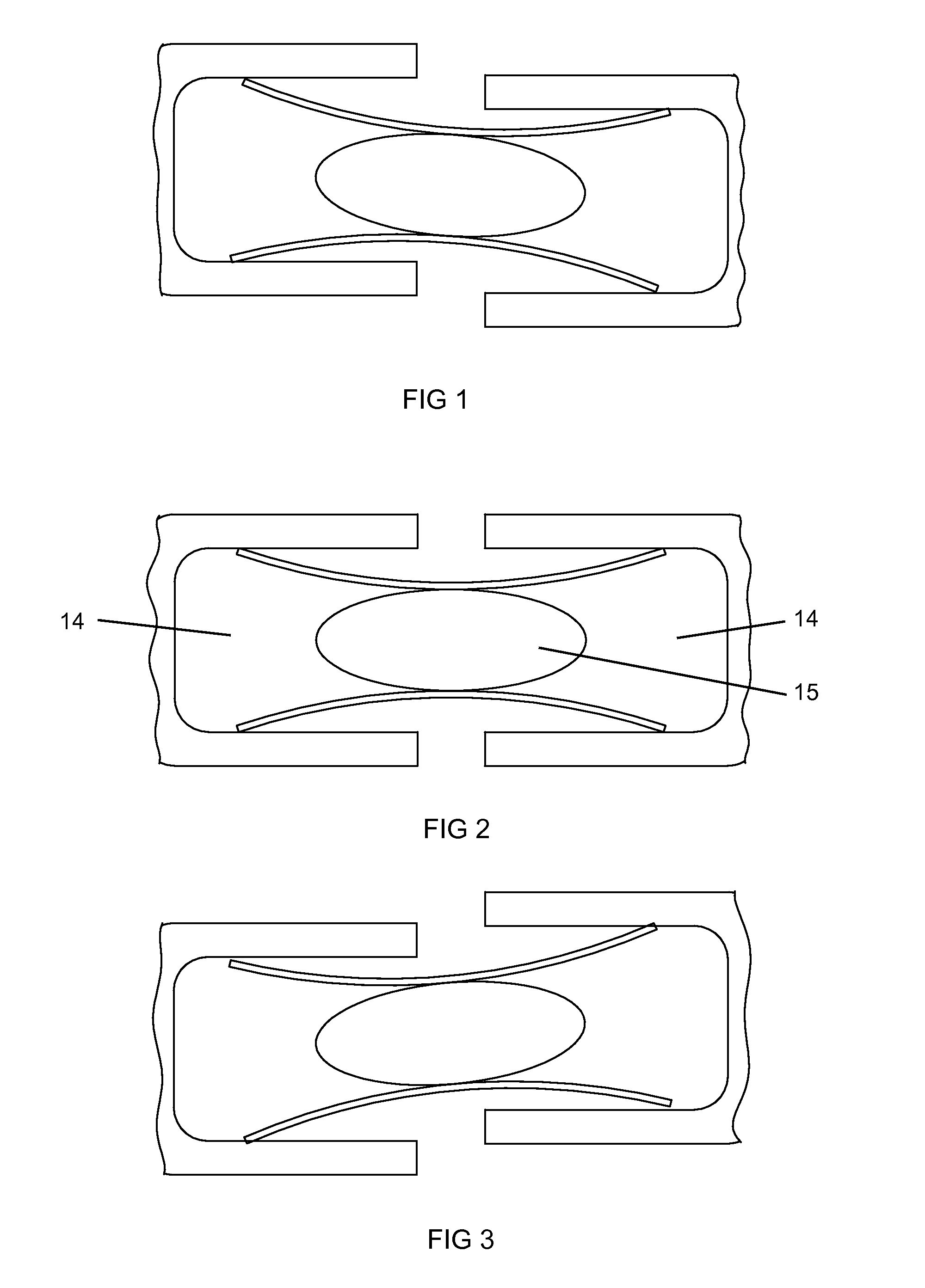
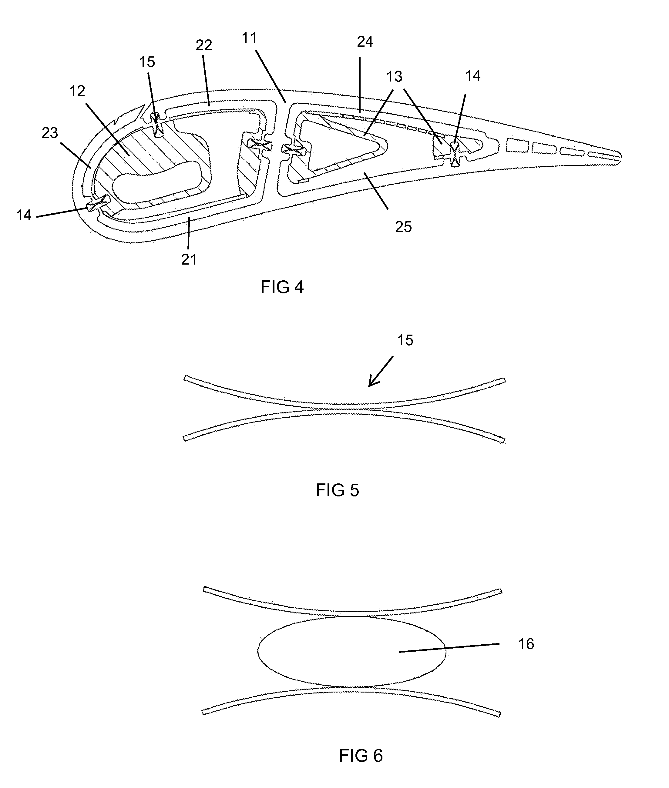
[0021]The present invention is a flexible or compliant seal that is used in a high temperature environment (such as that in a combustor or a turbine of a gas turbine engine) in which the two opposed seal slots in which the compliant seal is located is not aligned so that prior art rigid seals do not produce adequate sealing. The flexible seal of the present invention will provide a high sealing capability as the opposed two seal slots move with respect to one another. The compliant seal can be used on surfaces such as a combustor transition duct inter-segment gaps for blade outer air seals or duct segments, platform interfaces of turbine vanes, case-tied compressor stator vane segments, and seals between a spar and a shell in a spar and shell stator vane or rotor blade.

[0022]FIGS. 1 through 3 shows the flexible or compliant seal 15 of the present invention in opposed seal slots 14 with different alignments of the slots 14. FIG. 2 shows the slots 14 is alignment while FIG. 1 shows th...


PUM


Abstract

A flexible seal having an X-shaped cross section that forms four contact points on four contact surfaces of two opposed seal slots. The flexible seal is used for a component in which the two seal slots undergo a large deflection such that the opposed slots are not aligned and a rigid seal will not form an adequate seal. The flexible seal can be used in a component of a combustor or a turbine in a gas turbine engine where opposed seal slots undergo the large deflection during operation.

Description

GOVERNMENT LICENSE RIGHTS[0001]This invention was made with Government support under contract number DE-FE-0006696 awarded by Department of Energy. The Government has certain rights in the invention.CROSS-REFERENCE TO RELATED APPLICATIONS[0002]None.BACKGROUND OF THE INVENTION[0003]1. Field of the Invention[0004]The present invention relates generally to a gas turbine engine, and more specifically to a seal between opposing slots that suffer from relative movement.[0005]2. Description of the Related Art including information disclosed under 37 CFR 1.97 and 1.98[0006]In a gas turbine engine, such as a large frame heavy-duty industrial gas turbine (IGT) engine, a hot gas stream generated in a combustor is passed through a turbine to produce mechanical work. The turbine includes one or more rows or stages of stator vanes and rotor blades that react with the hot gas stream in a progressively decreasing temperature. The efficiency of the turbine—and therefore the engine—can be increased b...

Claims


Application Information

Patent Timeline
Patent Type & Authority Patents(United States)
IPC IPC(8): F01D5/18
CPCF01D5/189
Inventor MEMMEN, ROBERT LFEDOCK, JOHN ADOWNS, JAMES P
Owner FLORIDA TURBINE TECH
Why Eureka
Try Eureka