Wireless communication apparatus
a communication apparatus and wireless technology, applied in the field of radio communication devices, can solve the problems of radio communication blockage and significant shortening of communication distance, and achieve the effect of effective transmission ra
- Summary
- Abstract
- Description
- Claims
- Application Information
AI Technical Summary
Benefits of technology
Problems solved by technology
Method used
Image
Examples
first exemplary embodiment
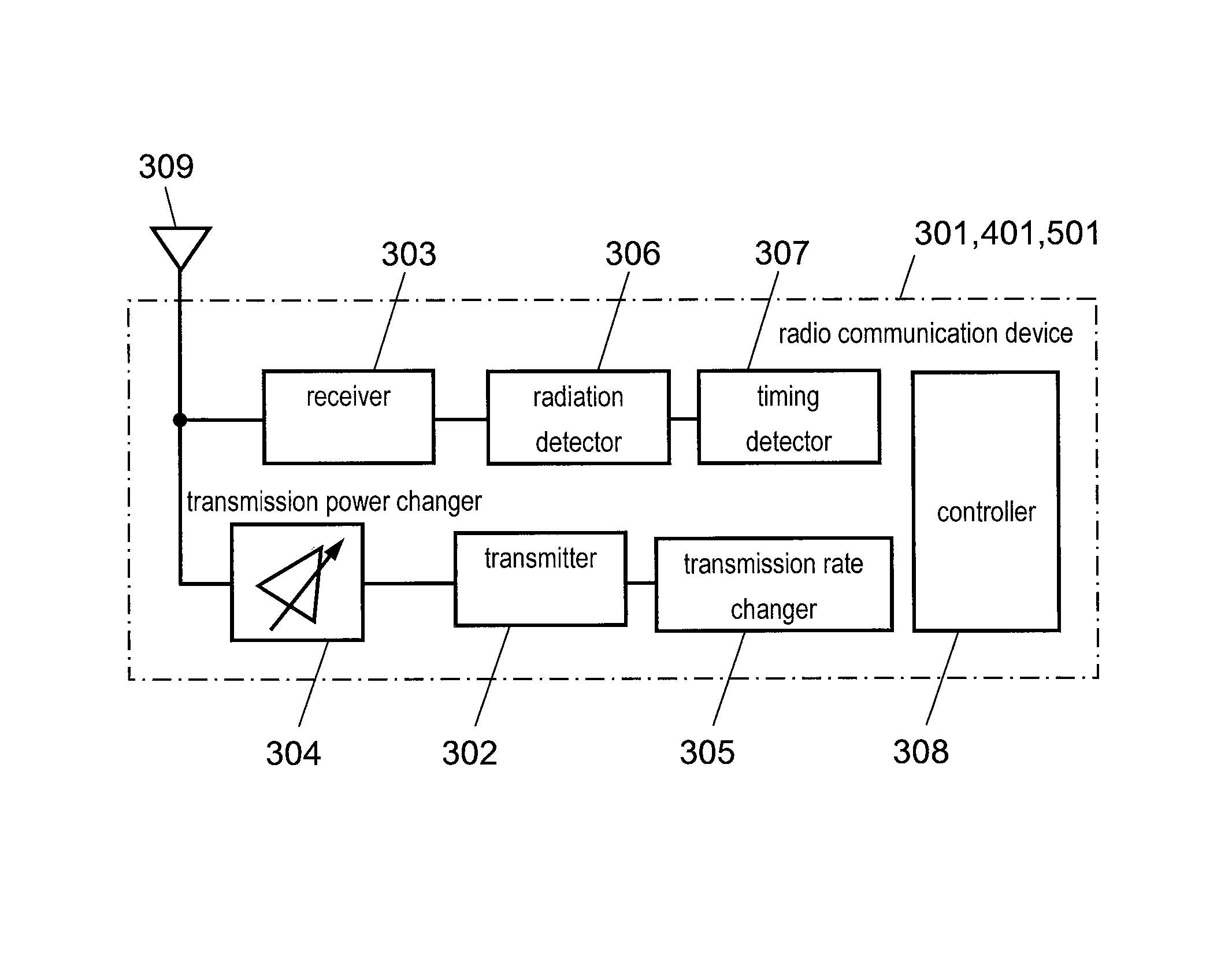
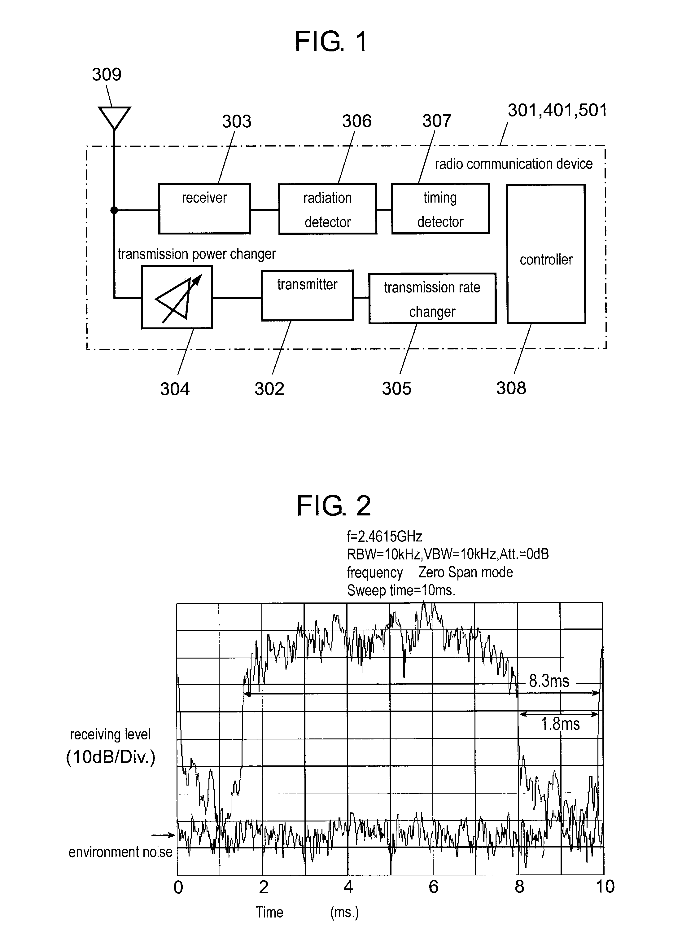
[0030]FIG. 1 is a block diagram showing the structure of a radio communication device in accordance with the first exemplary embodiment of the present invention. Radio communication device 301 has transmitter 302, receiver 303, transmission power changer 304, transmission rate changer 305, radiation detector 306, timing detector 307, controller 308, and antenna 309.
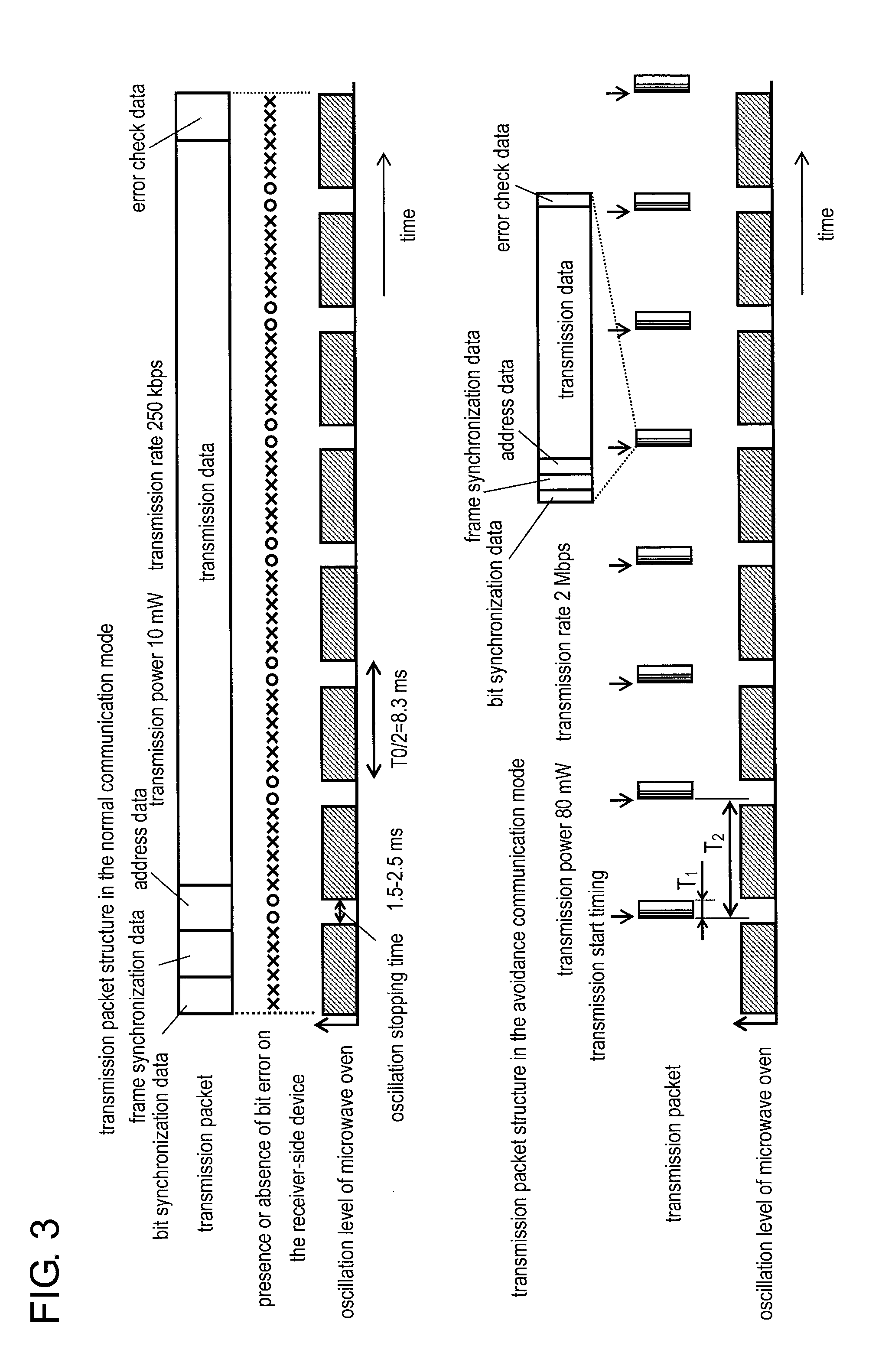
[0031]Radio communication device 301 transmits and receives data. Radio communication device 301 provides data communication at radio frequencies ranging from 2.4 GHz to 2.5 GHz. The communication channels are changeable. Radio communication device 301 transmits or receives data, switching between a normal communication mode and an avoidance communication mode (which will be described later). Radio communication device 301 employs frequency shift keying (FSK) modulation. In the normal communication mode, radio communication device 301 transmits data with a transmission power of 10 mW and at a transmission rate of 250 kbps...
second exemplary embodiment
[0062]The structure of the second exemplary embodiment is described. FIG. 6 shows the structure of a transmission packet of radio communication device 401 in accordance with the second exemplary embodiment. Radio communication device 401 has a structure nearly the same—except for the workings of timing detector 307—as that of radio communication device 301 of the first exemplary embodiment shown in FIG. 1. Instead of the normal communication mode described in the first embodiment, radio communication device 401 has a timing detection mode for timing detection. In the timing detection mode, radio communication device 401 transmits a transmission packet with transmission cycle T3 obtained by the following calculation: T3=T0 / 2+T4 (where, T4 represents a shift time and T4 is determined so as to satisfy the inequality: −T0 / 2≦T4≦T0 / 2). Having a structure the same as the divided packet in the avoidance communication mode, the transmission packet in the timing detection mode is transmitted ...
third exemplary embodiment
[0073]The first and the second exemplary embodiments explain an example where radio communication device 401 communicates with radio communication device 501 on the receiver side with no effect of radiation from a microwave oven. The structure shown in the third embodiment is a radio communication system containing a microwave oven (as a radio communication device that operates on a commercial power source) and a radio communication device, such as a radio communication terminal equipment and a radio remote control (as a radio communication device that operates on a battery power source). In the structure of the embodiment, the effect similar to that obtained by the previous two embodiments is expected.
[0074]FIG. 7 schematically shows radio communication system 400 in accordance with the third exemplary embodiment. Radio communication system 400 contains radio communication device 100 operating on a commercial power source and radio communication devices 200, 200′ operating on a bat...
PUM
 Abstract
Description
Claims
Application Information
 - R&D
- Intellectual Property
- Life Sciences
- Materials
- Tech Scout
- Unparalleled Data Quality
- Higher Quality Content
- 60% Fewer Hallucinations
Browse by: Latest US Patents, China's latest patents, Technical Efficacy Thesaurus, Application Domain, Technology Topic, Popular Technical Reports.
© 2025 PatSnap. All rights reserved.Legal|Privacy policy|Modern Slavery Act Transparency Statement|Sitemap|About US| Contact US: help@patsnap.com


