
Large area optical diagnosis apparatus and operating method thereof

a large-area optical diagnosis and operating method technology, applied in the field of optical diagnosis, can solve the problems of time-consuming and inconvenient, complicated structure of the oct diagnosis apparatus, limitations in practical applications, etc., and achieve the effect of enhancing diagnosis efficiency and saving a lot of tim

Active Publication Date: 2013-10-22
CRYSTALVUE MEDICAL
View PDF12 Cites 20 Cited by
  • Summary
  • Abstract
  • Description
  • Claims
  • Application Information

AI Technical Summary

Benefits of technology

The apparatus achieves efficient large-area diagnosis by simultaneous multi-point detection, significantly reducing diagnosis time and improving efficiency compared to conventional OCT systems.

Problems solved by technology

However, no matter the above-mentioned time-domain or frequency-domain OCT diagnosis apparatus, a galvo-mirror is needed in the light path to change diagnosis points, and the structure of the OCT diagnosis apparatus will become complicated.
In addition, because the time-domain and frequency-domain OCT diagnosis apparatus can only diagnose the diagnosis points one by one, it fails to perform a large-area diagnosis at the same time, so it is time-consuming and inconvenient, and has limitations in practical applications.

Method used


Image

  • Large area optical diagnosis apparatus and operating method thereof
  • Large area optical diagnosis apparatus and operating method thereof
  • Large area optical diagnosis apparatus and operating method thereof

Examples


first embodiment

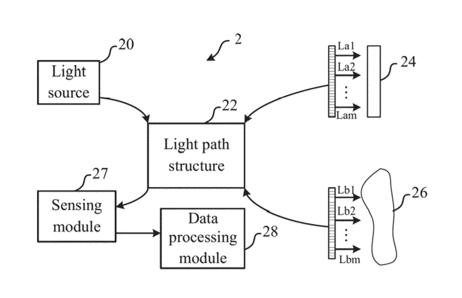
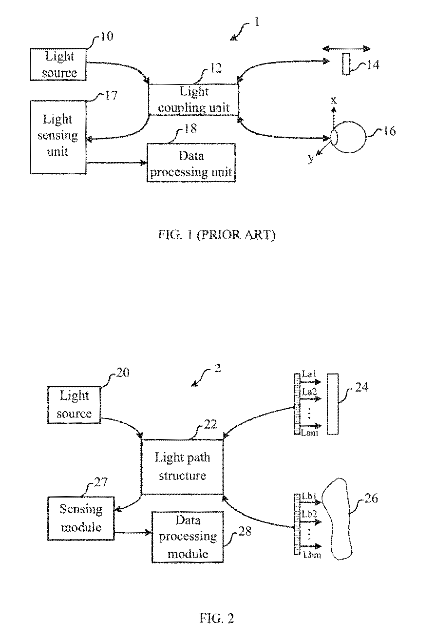
[0032]the invention is a large area optical diagnosis apparatus. In this embodiment, the large area optical diagnosis apparatus is used to diagnose an object to be diagnosed to obtain the optical data related to the vertical cross-section of the object to be diagnosed, but not limited to this. Please refer to FIG. 2. FIG. 2 illustrates a schematic figure of the large area optical diagnosis apparatus.

[0033]As shown in FIG. 2, the large area optical diagnosis apparatus 2 includes a light source 20, a light path structure 22, a reference end 24, an object to be diagnosed 26, a sensing module 27, and a data processing module 28. Wherein, the light source 20 at least emits a coherent light into the light path structure 22, and the light path structure 22 divides the coherent light into a plurality of first incident lights La1˜Lam and a plurality of second incident lights Lb1˜Lbm. The plurality of first incident lights La1˜Lam is emitted to the reference end 24 and the plurality of second...

second embodiment

[0054]the invention is a large area optical diagnosis apparatus operating method. In practical applications, the large area optical diagnosis apparatus is used to diagnose the object to be diagnosed to obtain the optical data related to the vertical cross-section of the object to be diagnosed.

[0055]In this embodiment, the large area optical diagnosis apparatus includes a light source, a light path structure, and a sensing module. The light path structure includes a plurality of optical units. Please refer to FIG. 10. FIG. 10 illustrates a flowchart of the large area optical diagnosis apparatus operating method.

[0056]As shown in FIG. 10, the method includes following steps. Firstly, in step S10, the light source at least emits a coherent light. Then, in step S12, the light path structure divides the coherent light into a plurality of first incident lights and a plurality of second incident lights, wherein the plurality of first incident lights is emitted toward an object to be diagno...


PUM


Abstract

A large area optical diagnosis apparatus and the operating method thereof are disclosed. The large area optical diagnosis apparatus includes a light source, a light path structure, and a sensing module. The light source is used to at least emit a coherent light. The light path structure includes a plurality of optical units used for dividing the coherent light into a plurality of first incident lights and a plurality of second incident lights. The plurality of first incident lights are emitted toward an object to be diagnosed and the plurality of second incident lights are emitted toward a reference end. The object to be diagnosed and the reference end reflect the plurality of first incident lights and the plurality of second incident lights to be a plurality of reflected lights. The sensing module senses the plurality of reflected lights to generate a sensing result related to the object to be diagnosed.

Description

BACKGROUND OF THE INVENTION[0001]1. Field of the Invention[0002]The invention relates to optical diagnosis, in particular, to a large area optical diagnosis apparatus and operating method thereof using re-designed light path structure and signal analysis unit to achieve the effect of synchronous multi-point optical coherence tomography (OCT) diagnosis.[0003]2. Description of the Prior Art[0004]In recent years, with the continuous progress of optical diagnosis technology, the optical image scan technology provides a non-invasive way to understand the composition and structure of the tissue of the object to be diagnosed. Because it has features of rapid and non-invasive, it is widely used in many regions, especially in medical diagnosis region. When the light is emitted into the tissue structure, with the various media in different depths, the light absorption characteristic and scattering characteristic will be also changed accordingly. And, the optical image scan technology uses dif...

Claims


Application Information

Patent Timeline
Patent Type & Authority Patents(United States)
IPC IPC(8): G01B9/02
CPCA61B5/0066A61B5/0073G01N21/4795G01B9/02019G01B9/02027G01B9/02091G01B2290/45
Inventor WANG, WILLIAMCHOU, CHUNG-CHENGTSAI, CHE-LIANG
Owner CRYSTALVUE MEDICAL
Learn More