
Manufacturing method for boundary acoustic wave device and boundary acoustic wave device

a manufacturing method and technology applied in piezoelectric/electrostrictive/magnetostrictive devices, impedence networks, etc., can solve the problems of difficult extraction of implanted ions, reduce the manufacturing cost of boundary acoustic wave devices, and facilitate implanted ions. , the effect of less ion implantation energy

Active Publication Date: 2013-10-29
MURATA MFG CO LTD
View PDF10 Cites 2 Cited by
  • Summary
  • Abstract
  • Description
  • Claims
  • Application Information

AI Technical Summary

Benefits of technology

[0010]Accordingly, preferred embodiments of the present invention provide a manufacturing method for a boundary acoustic wave device, which is capable of easily and certainly obtaining the boundary acoustic wave device including desired frequency characteristics, and the boundary acoustic wave device.
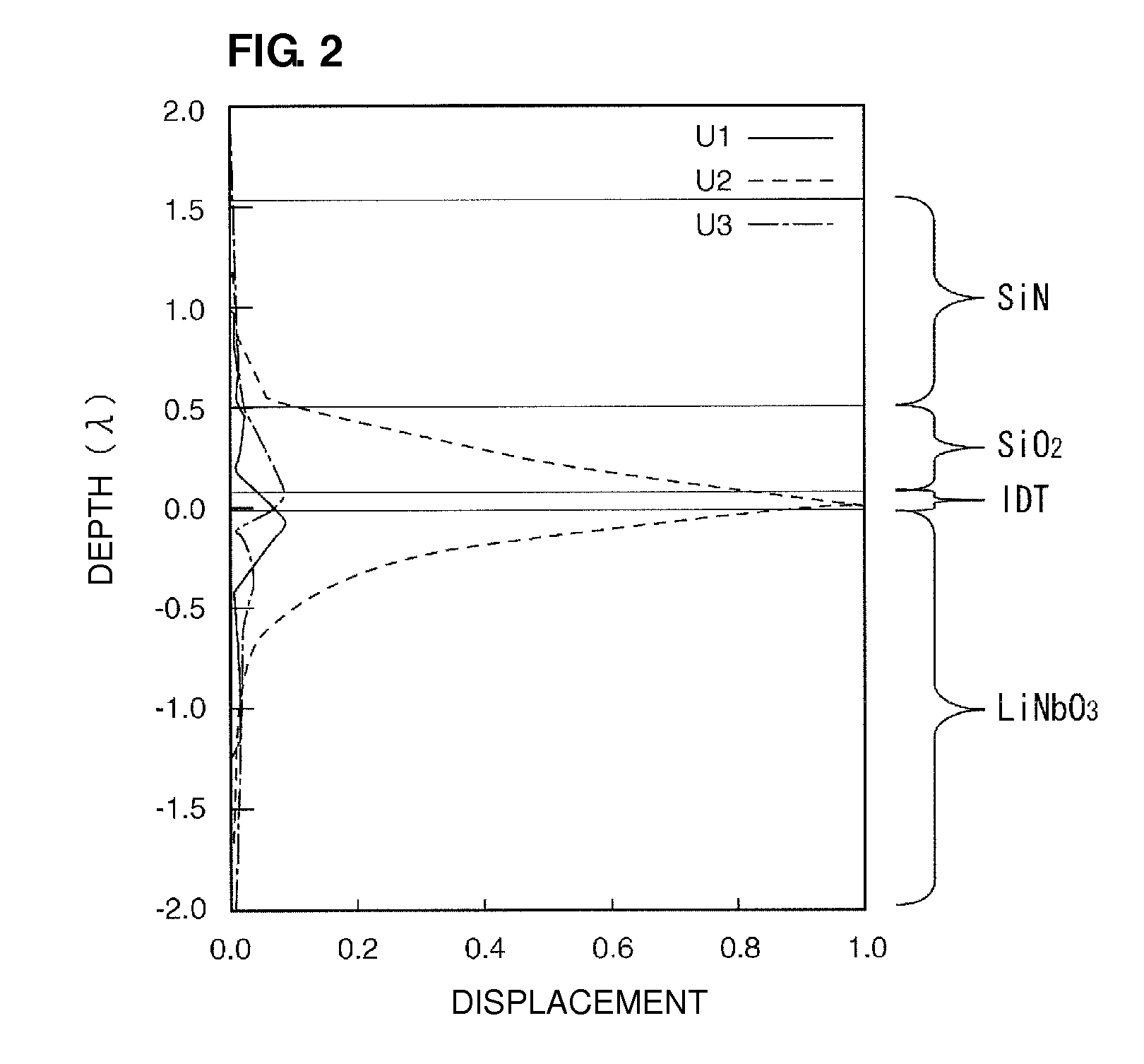
[0014]In another specific aspect of the manufacturing method for the boundary acoustic wave device according to a preferred embodiment of the present invention, in the process for preparing the laminated body, the second medium is formed so that the thickness of the second medium becomes a thickness causing elastic waves excited by the IDT electrode to mainly include not boundary acoustic waves but surface acoustic waves. Furthermore, after the ion implantation process, a third medium including the same dielectric material as the second medium or a dielectric material different from the second medium is further formed on the second medium so that elastic waves excited by the IDT electrode mainly include boundary acoustic waves. In this case, since the thickness of the second medium is thin, it is possible to perform adjustment of frequency using small ion implantation energy. Accordingly, it is possible to perform adjustment of frequency using low-priced equipment. In addition, since the thickness of the second medium is thin, it is possible to easily implant ions whose atomic weights are large. When ions of atoms whose atomic weights are large are implanted, frequency characteristics greatly change. Accordingly, it is possible to reduce the amount of ions implantation with respect to the amount of adjustment of frequency, and it is possible to easily perform adjustment of frequency.
[0018]In another specific aspect of the boundary acoustic wave device according to a preferred embodiment of the present invention, the thickness of the second medium is a thickness causing elastic waves excited by the IDT electrode to mainly include not boundary acoustic waves but surface acoustic waves, and further includes a third medium, which is laminated on the second medium and includes the same dielectric material as the second medium or dielectric material different from the second medium. The third medium is arranged so that elastic waves excited by the IDT electrode mainly include boundary acoustic waves. In this case, since the thickness of the second medium is thin, less ion implantation energy is necessary. Accordingly, since it is possible to perform adjustment of frequency using low-priced equipment, it is possible to reduce the manufacturing cost of the boundary acoustic wave device. In addition, it is possible to easily implant ions whose atomic weights are large. Therefore, it is possible to easily perform adjustment of frequency.
[0019]According to the manufacturing method for the boundary acoustic wave device and the boundary acoustic wave device according to various preferred embodiments of the present invention, at a stage where the laminated body in which the IDT electrode is disposed at the interface between the first and second media is obtained, it is possible to adjust a frequency owing to the ion implantation. Accordingly, after the completion of the boundary acoustic wave device, it is possible to easily adjust the frequency so as to obtain target frequency characteristics. Alternatively, after the second medium has been formed so that elastic waves excited by the IDT electrode mainly include surface acoustic waves, it is possible to easily adjust the frequency owing to the ion implantation.
[0020]In addition, since the frequency is adjusted owing to the ion implantation, it is possible to certainly distribute ions to a portion near the interface between the first and second media. Therefore, it is possible to perform adjustment of frequency with a high degree of accuracy. According to various preferred embodiments of the present invention, it is possible to easily and certainly provide the boundary acoustic wave device including target frequency characteristics.

Problems solved by technology

In this case, since the ions of atoms whose atomic weights are large are implanted, the implanted ions are difficult to be extracted.

Method used


Image

  • Manufacturing method for boundary acoustic wave device and boundary acoustic wave device
  • Manufacturing method for boundary acoustic wave device and boundary acoustic wave device
  • Manufacturing method for boundary acoustic wave device and boundary acoustic wave device

Examples


Embodiment Construction

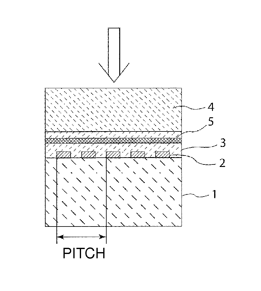
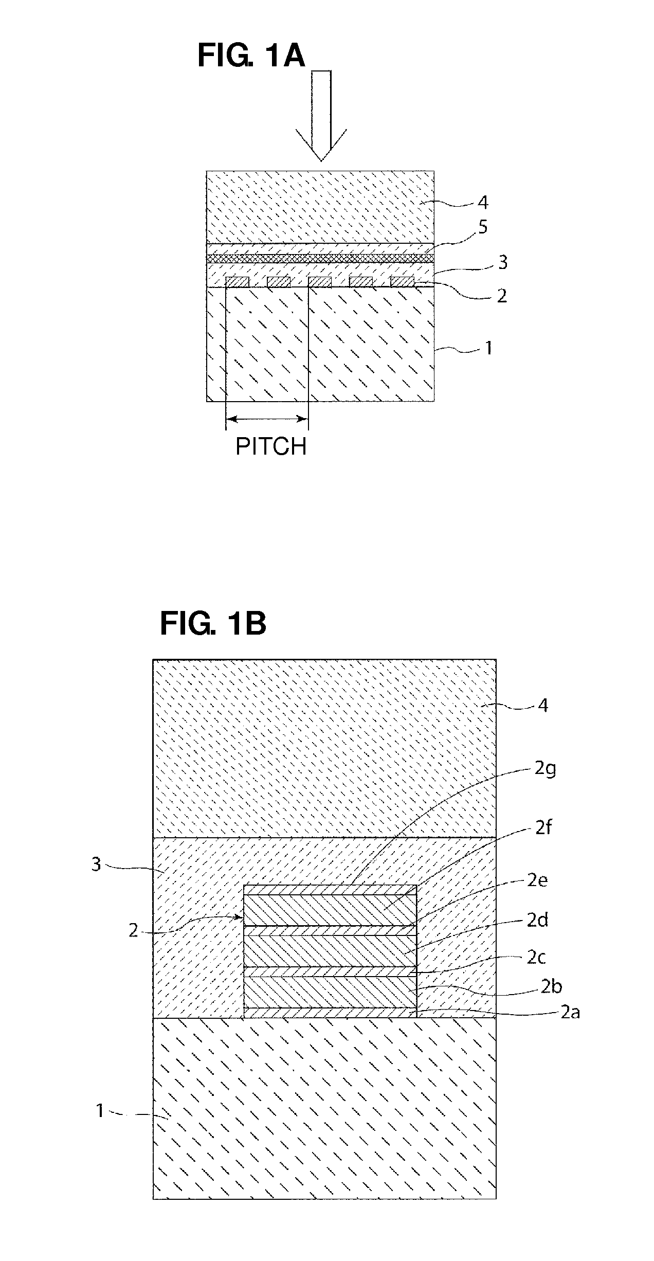
[0034]Hereinafter, specific preferred embodiments of the present invention will be described with reference to drawings, thereby clarifying the present invention.

[0035]A manufacturing method for a boundary acoustic wave device according to a preferred embodiment of the present invention will be described with reference to FIGS. 1A and 1B. First, a first medium 1 illustrated in FIG. 1A is prepared. As the first medium 1, in the present preferred embodiment, a substantially 25-degree Y-cut LiNbO3 substrate is preferably used, for example. As a matter of fact, the first medium 1 may also be formed using another piezoelectric substance. As such a piezoelectric substance, LiNbO3 whose Cut-Angles are other than the above-mentioned Cut-Angles, LiTaO3, crystal, piezoelectric ceramics, or other suitable material may be used, for example. In addition, as the piezoelectric body, a laminated body including a piezoelectric film and a supporting substrate may be used in which the piezoelectric fi...


PUM

PropertyMeasurementUnit
wave lengthaaaaaaaaaa
widthaaaaaaaaaa
thicknessaaaaaaaaaa

Abstract

A manufacturing method for a boundary acoustic wave device is capable of certainly providing the boundary acoustic wave device with desired target frequency characteristics. The manufacturing method for the boundary acoustic wave device includes a process for preparing a laminated body that includes a first medium, a second medium laminated on the first medium, and an IDT electrode that is disposed at an interface between the first and second media, and a process for implanting ions from an outer portion of the second medium and adjusting a frequency.

Description

BACKGROUND OF THE INVENTION[0001]1. Field of the Invention[0002]The present invention relates to a manufacturing method for a boundary acoustic wave device preferably for use in a resonator, a bandpass filter, or the like, for example, and the boundary acoustic wave device, and also relates to a manufacturing method for a boundary acoustic wave device, which includes a process for adjustment of a frequency, and the boundary acoustic wave device, in more detail.[0003]2. Description of the Related Art[0004]In recent years, in place of surface acoustic wave devices, boundary acoustic wave devices have been drawing attention. In the boundary acoustic wave device, boundary acoustic waves propagate through a boundary between first and second media made of solid substances. Accordingly, in the boundary acoustic wave device, compared with a surface acoustic wave device, it is possible to promote the downsizing of the device. In addition, it is possible to achieve the simplification of a pac...

Claims


Application Information

Patent Timeline
Patent Type & Authority Patents(United States)
IPC IPC(8): H01L41/08H03H3/10H03H9/145
CPCH03H3/10H03H9/0222H01L41/253Y10T29/42H03H2003/0414H10N30/04
Inventor KANDO, HAJIMESAJI, MARI
Owner MURATA MFG CO LTD
Learn More