Process for producing alkali metal hydrogencarbonate

a technology of alkali metal hydrogencarbonate and process, which is applied in the direction of alkali metal carbonates, lithium carbonates/bicarbonates, inorganic chemistry, etc., can solve the problems of reducing the yield of large crystals, increasing the proportion of fine particulate crystals, and increasing the total number of crystals, so as to achieve easy and certainly control the apparent number of nuclei, large particle size, and excellent flowability

Inactive Publication Date: 2006-08-31
ASAHI GLASS CO LTD
View PDF4 Cites 17 Cited by
  • Summary
  • Abstract
  • Description
  • Claims
  • Application Information

AI Technical Summary

Benefits of technology

[0017] According to the present invention, in the crystallization method from an aqueous solution, it is possible to easily and certainly control the apparent number of nuclei formed in an industrial scale, whereby an industrial production of an alkali metal hydrogenc

Problems solved by technology

For example, sodium hydrogencarbonate is usually difficult to grow to large particles and tends to have a small average particle size, since nuclei tend to be formed in a large amount during crystallization, whereby the proportion of fine particulate crystals will increase, and the total number of crystals will increase.
And, if such fine particulate or small crystals increase, it is likely that the yield of large crystals will decrease, and further the subsequent operation such as separation, washing, drying or classification of the solid tends to be difficult.
However, if a crystal habit modifier is used, the crystal habit is likely to be changed, whereby the crystal state may be changed, and since the effects will be obtained under specific conditions, it has been difficult to use such a method in combination with other methods.
Further, the crystal habit modifier may remain in crystals thereby to lower the purity of the crystals, whereby the application of the product tends to be limited.
However, in this method, the crystallization load per unit time and unit volume of the crystallization equipment is required to be low, whereby

Method used


Image

  • Process for producing alkali metal hydrogencarbonate

Examples


example 1

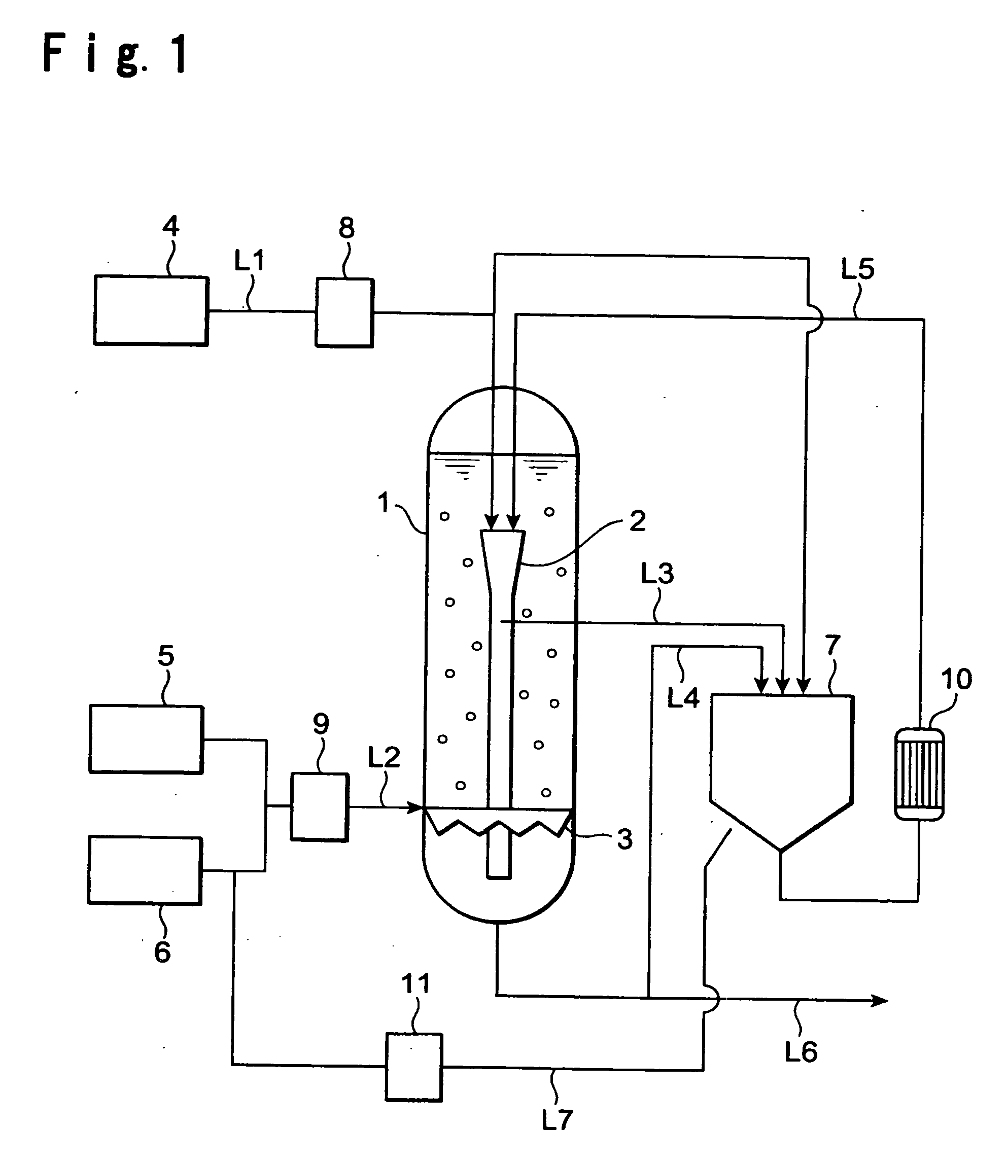
[0050] To the crystallizer 1, the raw material solution was supplied constantly at a rate of 100 kg / hr by the raw material solution supply line L1, and at the same time, a mixed gas of carbon dioxide at a concentration of from 40 to 43% / air was continuously supplied by the carbon dioxide blowing line L2 at a flow rate of 30 m3 / hr (standard state).

[0051] Further, from the inner cylinder 2 in the crystallizer 1, the slurry was withdrawn at a rate of 800 kg / hr by the slurry withdrawing line L3 into the dissolution apparatus 7 (inner diameter: 0.4 m, height: 3.1 m) and returned to the atmospheric pressure. Further, this liquid was returned to the inlet (upper side) of the inner cylinder2 via the heat exchanger 10 (temperature: 67° C.) by the slurry recycling line L5. The amount of the slurry withdrawn from the crystallizer 1 by the slurry withdrawing line L6, was adjusted depending upon the amount of the raw material solution supplied to maintain the liquid level in the crystallizer 1 ...

example 3

[0054] Into the crystallizer 1, the raw material solution was supplied constantly at a rate of 200 kg / hr by the raw material solution supply line L1, and at the same time, a mixed gas of carbon dioxide at a concentration of from 40 to 43% / air was continuously supplied by the carbon dioxide blowing line L2 at a flow rate of 54 m3 / hr (standard state).

[0055] Further, from the inner cylinder 2 in the crystallizer 1, the slurry was withdrawn at a rate of 1,200 kg / hr by the slurry withdrawing line L3 into the dissolution apparatus 7 and returned to the atmospheric pressure. Further, air was passed through the membrane filter 11 of 0.1 μm and then blown at a rate of 120 liter / hr (standard state) from the air blowing line L7, and then, this liquid was returned to the inlet (the upper side) of the inner cylinder 2 via the heat exchanger 10 (temperature: 82° C.) by the slurry recycling line L5. The amount of the slurry withdrawn from the crystallizer 1 by the slurry withdrawing line L6 was a...

example 4

[0057] To the crystallizer 1, the raw material solution was supplied constantly at a rate of 110 kg / hr by the raw material solution supply line L1, and at the same time, a mixed gas of carbon dioxide at a concentration of from 40 to 43% / air was continuously supplied by the carbon dioxide supply line L2 at a flow rate of 54 m3 / hr (standard state).

[0058] Further, from the inner cylinder 2 in the crystallizer 1, the slurry was withdrawn at a rate of 800 kg / hr by the slurry withdrawing line L3 into the dissolution apparatus 7, and returned to the atmospheric pressure. Air was passed through the membrane filter 11 of 0.1 μm and then blown from the air blowing line L7 at is a rate of 120 liter / hr (standard state), and then, this liquid was returned to the inlet (the upper side) of the inner cylinder 2 via the heat exchanger 10 (temperature: 67° C.) by the slurry recycling line L5. At that time, to the dissolution apparatus 7, an aqueous sodium hydroxide solution was supplied constantly a...


PUM


Abstract

To provide a process for easily obtaining an alkali metal hydrogencarbonate having a large crystal particle size in good yield by an industrially convenient installation by a crystallization method from an aqueous solution. A process for producing an alkali metal hydrogencarbonate, which comprises reacting an aqueous solution containing alkali metal ions with carbon dioxide in a prescribed crystallizer to precipitate crystals of an alkali metal hydrogencarbonate, characterized in that a part of a slurry containing the above crystals in the above aqueous solution, is withdrawn from the above crystallizer and, after a part of the above crystals is dissolved, returned to the above crystallizer.

Description

TECHNICAL FIELD [0001] The present invention relates to a process for producing an alkali metal hydrogencarbonate. BACKGROUND ART [0002] An alkali metal hydrogencarbonate such as sodium hydrogencarbonate is produced by crystallization from an aqueous solution. For example, carbon dioxide is blown into an aqueous solution containing sodium ions to obtain sodium hydrogencarbonate crystals formed by a reaction. As the solution containing sodium ions, an aqueous solution containing sodium carbonate or sodium hydroxide, or so-called ammonia brine obtained by blowing ammonia into a sodium chloride solution, is employed. [0003] For example, sodium hydrogencarbonate is usually difficult to grow to large particles and tends to have a small average particle size, since nuclei tend to be formed in a large amount during crystallization, whereby the proportion of fine particulate crystals will increase, and the total number of crystals will increase. Formation of nuclei is likely to be remarkabl...

Claims


Application Information

Patent Timeline
IPC IPC(8): C01D7/00C01D15/08C01D17/00
CPCC01D7/10
Inventor NAKASHIMA, FUMIAKIARIMA, HISAKAZUKIKUCHI, SHINTAROHIRANO, HACHIRO
Owner ASAHI GLASS CO LTD
Why Eureka
Try Eureka