Image forming apparatus and method for adjusting the interval between a write head and a photoreceptor

a technology of image forming apparatus and write head, which is applied in the direction of electrographic process apparatus, power drive mechanism, instruments, etc., can solve the problems of long operation time, large variance, and difficulty in assembling mass-produced image forming apparatus, and achieves high accuracy of adjusting the interval. , the effect of easy and certainly checking

Inactive Publication Date: 2009-09-15
SHARP KK
View PDF12 Cites 20 Cited by
  • Summary
  • Abstract
  • Description
  • Claims
  • Application Information

AI Technical Summary

Benefits of technology

[0015]An object of the present invention is to provide an image forming apparatus that includes an adjusting mechanism enabling an unskilled user to easily and certainly check an interval between a write head and a photoreceptor to adjust the interval highly accurately, and a method of adjusting the interval between the write head and the photoreceptor.
[0016]Another object of the present invention is to provide an image forming apparatus that adjusts an interval between a write head and a photoreceptor when a photoreceptor drum is located at a predetermined rotation position to prevent the interval between the write head and the photoreceptor from becoming too small or too large in one rotation of the photoreceptor drum and making a photoreceptor surface out of a range of focal depth of the write head even if acceptable eccentricity, deformation, diameter variance, etc., are generated in the photoreceptor drum, and a method of adjusting the interval between the write head and the photoreceptor.
[0017]Another object of the present invention is to provide an image forming apparatus that corrects a shift between a regulating member and a photoreceptor drum in a sub-scanning direction when adjusting an interval between a write head and a photoreceptor and that subsequently adjusts the interval between the write head and the photoreceptor to accurately adjust the interval between the write head and the photoreceptor, and a method of adjusting the interval between the write head and the photoreceptor.

Problems solved by technology

However, it is difficult to assemble mass-produced image forming apparatuses such that intervals between the write heads and the photoreceptors become completely the same, and some variance is generated at the time of assembly.
Since the apparatus of the above dedicated jig is large and expensive, the dedicated jig cannot be used when a service person visits a customer's site to adjust the LED head position, and since the position is adjusted by performing test print and visually checking printed line widths, this operation takes a long time and adjustment accuracy is low in reality.
The mounting adjustment of image writing members such as an optical unit and LED head must be performed every time an electrostatic latent image support (photoreceptor) is replaced in addition to the above maintenance and, since the adjustment operation is difficult, the adjustment has been omitted at the time of the replacement of the photoreceptor in a normal process.
In recent years, print resolution is increased from conventional 300 dpi to 600 and 1200 dpi as higher quality images are formed by image forming apparatuses, and it is difficult even for a skilled service man to respond such increment with the conventional adjustment technique.
Therefore, if the interval adjustment is performed at a position where the distance is maximized between the write head and the photoreceptor, the distance between the write head and the photoreceptor drum becomes too small at other positions; contrary, if the interval adjustment is performed at a position where the distance is minimized between the write head and the photoreceptor, the distance between the write head and the photoreceptor drum becomes too large at other positions; and in either case, the optimum interval adjustment cannot be performed.

Method used


Image

  • Image forming apparatus and method for adjusting the interval between a write head and a photoreceptor
  • Image forming apparatus and method for adjusting the interval between a write head and a photoreceptor
  • Image forming apparatus and method for adjusting the interval between a write head and a photoreceptor

Examples


first embodiment

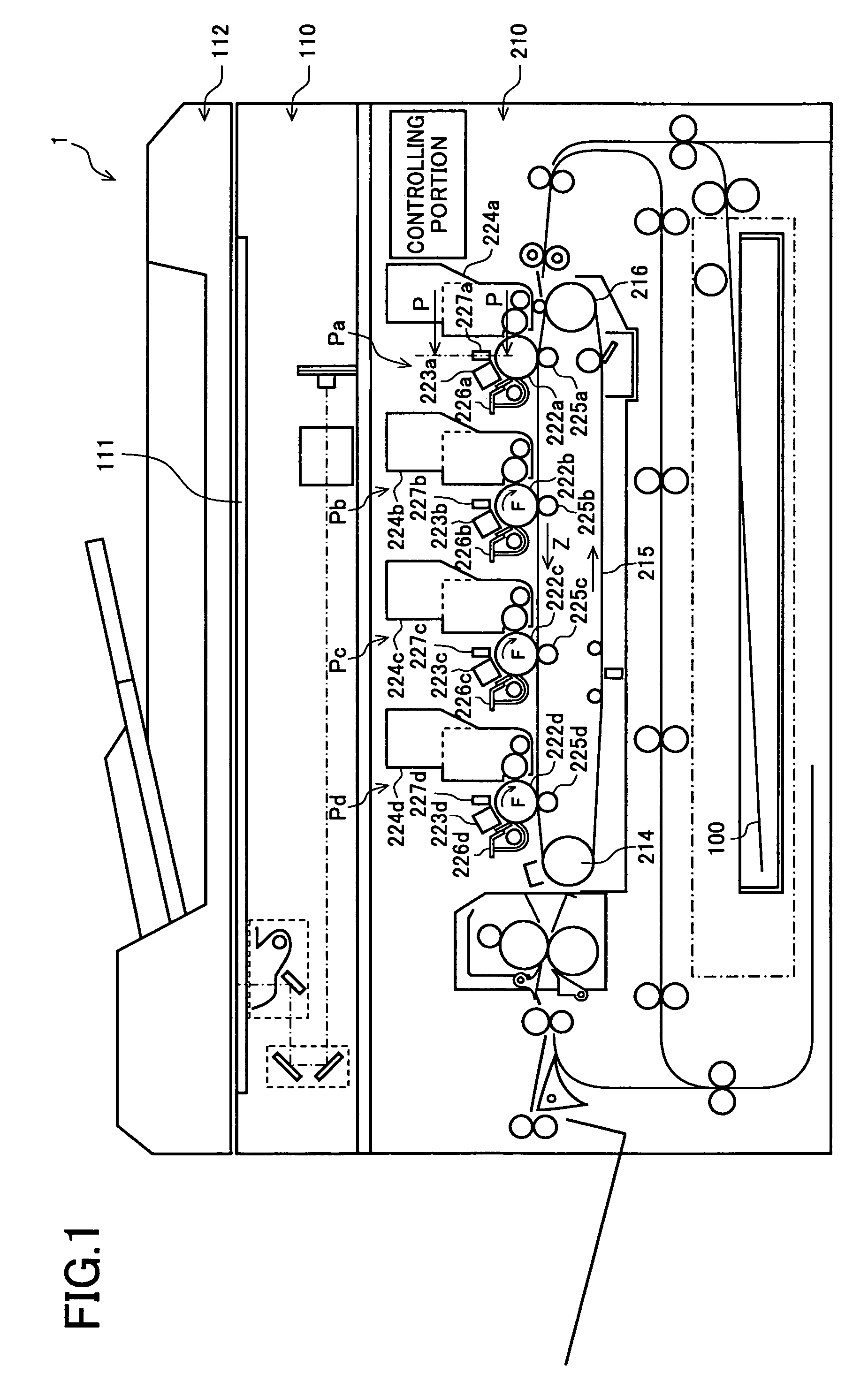
[0068]FIG. 1 is a sectional view of an overall configuration of a digital color copier that is an image forming apparatus of an embodiment of the present invention. An image forming apparatus 1 of the embodiment includes a document table 111 and an operation panel in the upper portion of the main body and includes an image reading portion 110 and an image forming portion 210 within the main body. On the upper surface of the document table 111, a reversing automatic document feeder (RADF) 112 is disposed and supported openable / closable to the document table 111 with a predetermined positional relationship with the document table 111.

[0069]The image forming apparatus 1 is an electrophotographic digital color copier that can copy a color image, reads an image of a document placed on the document table 111 or an image of a document fed by the reversing automatic document feeder 112 with the image reading portion 110, and reproduce the image of the read document on recording paper 100 wi...

second embodiment

[0105]FIGS. 13A to 13D depict a procedure of adjusting the interval between the write head and the photoreceptor in an image forming apparatus of a second embodiment. In the image forming apparatus of the first embodiment, after the regulating members 7a, 7b come in contact with the non-photoreceptor application portions 234a, 234b of the photoreceptor drum, the regulating member 7 is moved together with the LED head 227 in the direction away from the photoreceptor by the predetermined interval (B). On the other hand, the image forming apparatus of the second embodiment includes a mechanism that mounts spacers 235a, 235b with a thickness (B) corresponding to the predetermined interval described in the image forming apparatus of the first embodiment to a position corresponding to the non-photoreceptor application portion 234 on the photoreceptor drum; a moving mechanism that integrally moves the first and second regulating members 7a, 7b with the write head toward the photoreceptor t...

third embodiment

[0111]An image forming apparatus of a third embodiment relates to adjustment of the mounting position of the write head when eccentricity is generated in the photoreceptor drum 222 for some reason and the interval between the write head 227 and the photoreceptor drum 222 fluctuates periodically in one rotation of the photoreceptor drum. Although it is desirable that the interval between the write head 227 and the photoreceptor drum 222 is not fluctuated during one rotation of the photoreceptor drum 222, if the fluctuation range falls within a predetermined range, the photoreceptor drum 222 can be used to acquire a predetermined image quality.

[0112]FIGS. 15A to 15C depict defective shapes generated in the photoreceptor drum. In the case of the defective shape generated in the photoreceptor drum of FIG. 15A, although the diameter of the photoreceptor drum 222 should be an ideal shape shown by a dotted line, the diameter is larger (or smaller) as shown by a solid line and does not fall...


PUM


Abstract

An image forming apparatus comprises an adjusting mechanism that adjusts an interval between an LED head writing an optical image on a photoreceptor and a photoreceptor drum to a reference interval (A), and the adjusting mechanism includes a regulating member attached to the LED head. In the adjustment of the interval between the LED head and the photoreceptor drum, the LED head and the regulating member are integrally moved until the regulating member comes into contact with the photoreceptor drum. The interval between the LED head and the photoreceptor drum is (A-B) at this point. The LED head and the regulating member are moved in the direction opposite to the photoreceptor drum by a distance (B). As a result, the interval between the LED head and the photoreceptor drum is set to the reference interval (A).

Description

CROSS-NOTING PARAGRAPH[0001]This Nonprovisional application claims priority under 35 U.S.C. §119 (a) on Patent Application No. 2005-350852 filed in JAPAN on Dec. 5, 2005, the entire contents of which are hereby incorporated herein by references.FIELD OF THE INVENTION[0002]The present invention relates generally to an image forming apparatus and an adjusting method of an image forming apparatus, and, more particularly, to an image forming apparatus with an adjusting mechanism that adjusts an interval between a write head writing an optical image on a photoreceptor and the photoreceptor to a reference interval, and an adjusting method of the image forming apparatus.BACKGROUND OF THE INVENTION[0003]A write head such as an LED (Light Emitting Diode) head is used in an electrophotographic image forming apparatus such as a digital multi-function peripheral (MFP), printer, and facsimile machine and is positioned and attached with a predetermined interval from a photoreceptor drum to achiev...

Claims


Application Information

Patent Timeline
Patent Type & Authority Patents(United States)
IPC IPC(8): G03G13/04B41J2/435B41J25/308
CPCB41J25/304G03G15/04054G03G21/1666G03G2215/0409
Inventor FUKUTOME, SHOHICHIODA, AYUMUMOTOYAMA, TAKAHARUOKADA, TOMOHIKO
Owner SHARP KK
Why Eureka
Try Eureka