Metallic cover having IC tag, and metallic container

a technology of ic tags and metal covers, applied in the field of metal covers, can solve the problems of insufficient merchandise information displayed, bar codes having a certain limit, and reading will become impossible, and achieve the effect of preventing deterioration of ic tags performance, preventing ic tags from deteriorating, and maintaining the communication distance of ic tags to readers/writers

Active Publication Date: 2013-10-29
TOYO SEIKAN KAISHA LTD
View PDF12 Cites 3 Cited by
  • Summary
  • Abstract
  • Description
  • Claims
  • Application Information

AI Technical Summary

Benefits of technology

[0069]According to the present invention, due to the provision of a matching circuit for matching impedances between the antenna and the IC chip, the IC chip and the antenna can conduct matching of impedances by a matching circuit, whereby communication can be conducted without deterioration of an IC tag performance. As a result, the communication distance of the IC tag to a reader / writer can be kept long.
[0070]Further, by allowing the IC chip to electrically contact the metallic cover, it is possible to allow the metallic cover itself to function as the antenna of an IC tag, whereby the metallic cover and the IC chip can be integrated to form an IC tag. As a result, the necessary antenna length can be ensured while downsizing the tag main body, the influence of metals on communication properties can be eliminated, the tag becomes less visible so that the appearance of the metallic containers or the like can be kept favorable, and good wireless communication can be conducted between a reader / writer.
[0071]Therefore, according to the present invention, it is possible to realize a metallic cover provided with an IC tag which is particularly suitable for use in metallic containers such as an aluminum can or a steel can.
[0072]Further, according to the present invention, it is possible to allow the metallic cover itself to function as the antenna of an IC tag, since the pull-tab is formed into a predetermined shape and the IC chip is allowed to electrically contact this tab.
[0073]Further, by allowing the pull-tab which functions as the antenna to be formed into a predetermined shape, impedances of an IC chip and the antenna can be matched, whereby a metallic cover with sufficient communication properties can be realized.
[0074]With such a configuration, it becomes possible to realize a metallic cover provided with an IC tag which is suitable for metallic containers such as an aluminum can or a steel can in which a necessary antenna length is ensured while downsizing the tag main body and influence of communication properties by metals can be avoided, and as a result, the tag becomes seemingly less visible, and appearance or the like of metallic containers can be kept favorable, whereby good wireless communication can be conducted between the tag and a reader / writer.

Problems solved by technology

As a result, the area of a display surface or the character displayed, the number of characters, etc. are limited, and as a result, there was a problem that sufficient merchandise information was not displayed.
Moreover, reading will become impossible due to the presence of crack, dirt, etc., and since the amount of information which can be coded by a bar code is restricted, the bar code had a certain limit as a means to display and recognize merchandise information as in the case of the display in a character.
When such an IC tag is attached to a metallic container such as an aluminum can or a steel can, the IC tag is adversely affected by the conductivity of the metallic container, and, as a result, a problem occurred accurate wireless communication becomes impossible.
For this reason, when a tag is attached to a metallic container, heat loss etc., which is caused by absorption by the metallic container of magnetic waves and electromagnetic waves emitted by an antenna part arise, whereby communication properties of the tag may be deteriorated.
When a common IC tag which is used widely is attached to a metallic container as it is in this way, a problem arises that a tag malfunctions or wireless communications with a reader-writer cannot be conducted.

Method used


Image

  • Metallic cover having IC tag, and metallic container
  • Metallic cover having IC tag, and metallic container
  • Metallic cover having IC tag, and metallic container

Examples


first embodiment

[0111]The metallic cover provided with an IC tag and the metallic container provided with this metallic cover according to the first embodiment of the present invention will be explained with reference to FIGS. 1 to 9.

(Metallic Container)

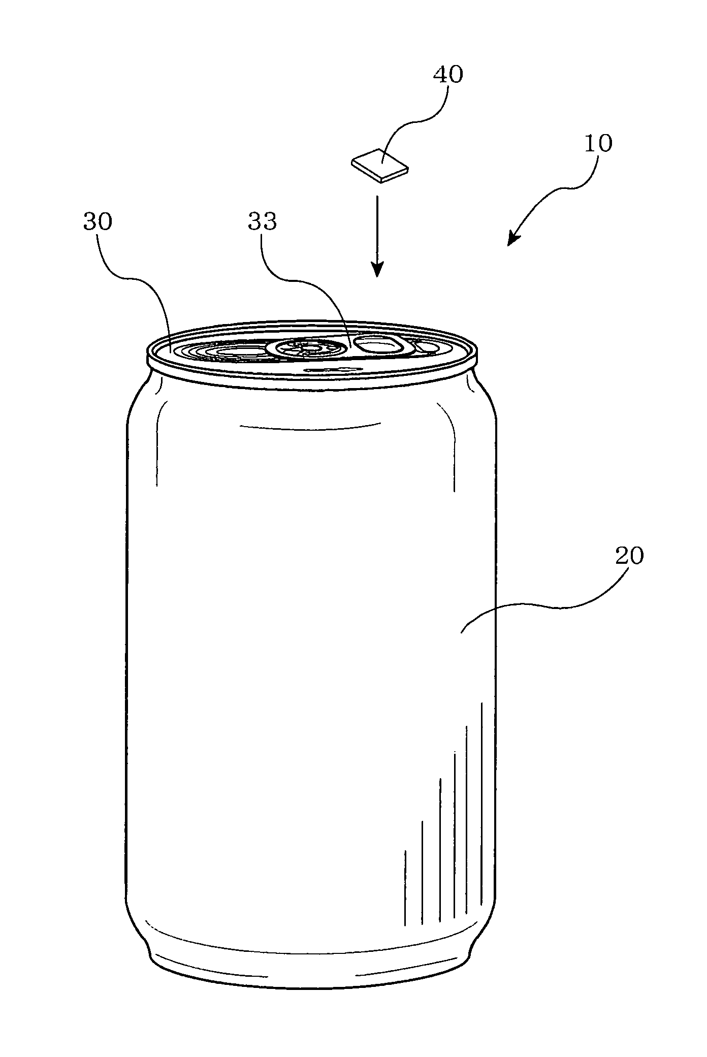
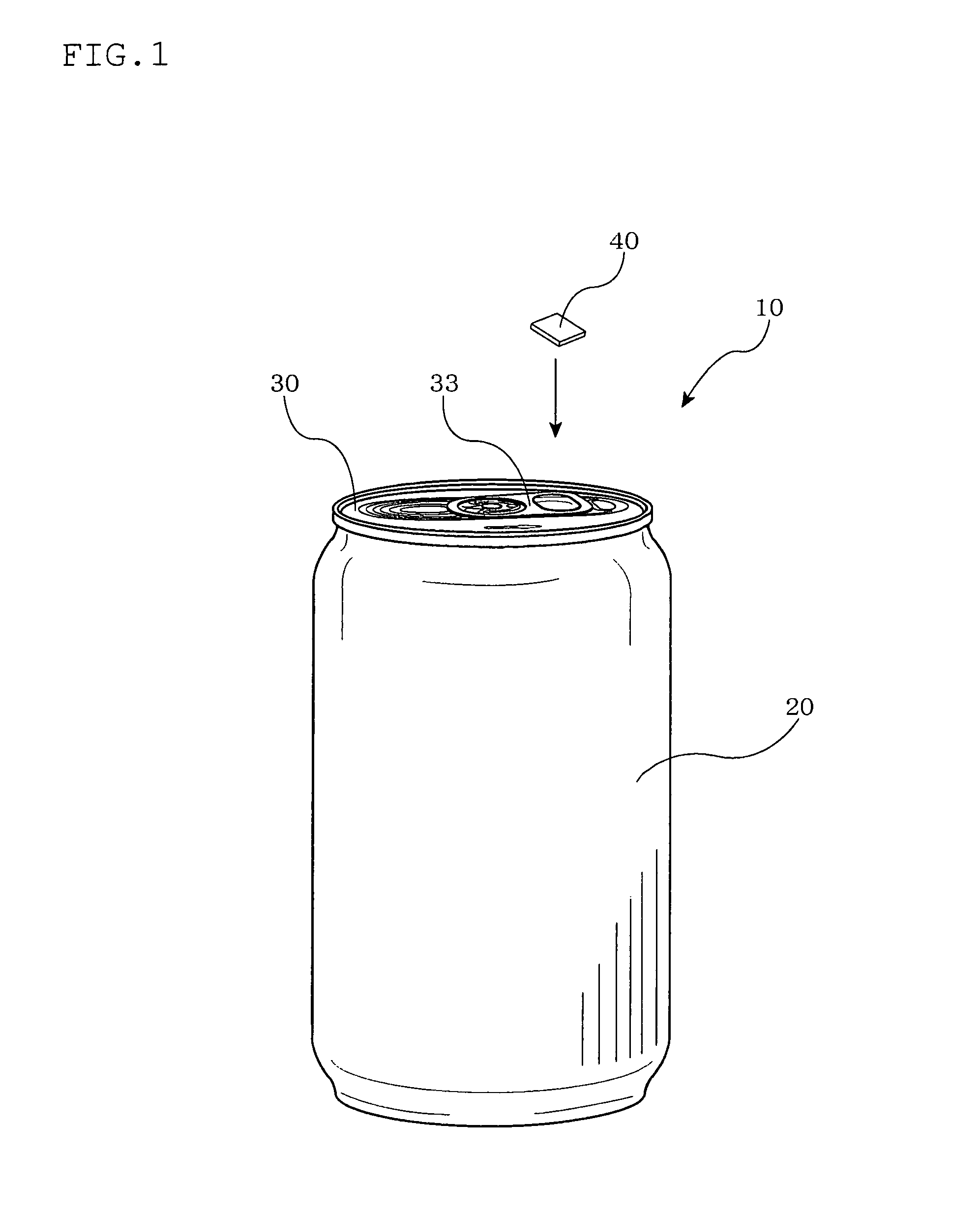
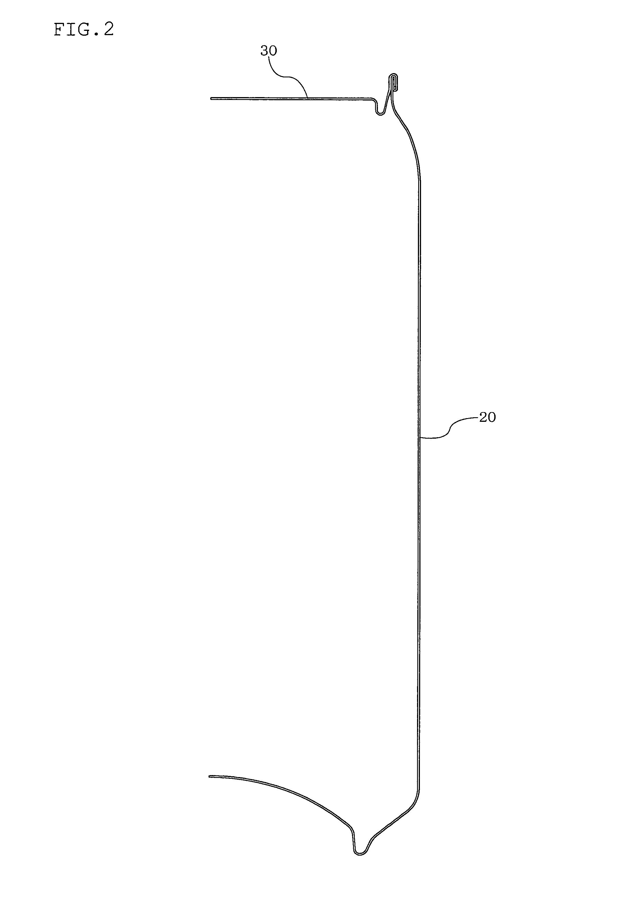
[0112]FIG. 1 is a perspective view showing the metallic container provided with an IC tag according to the first embodiment of the present invention. FIG. 2 is a partial cross-sectional view showing the metallic container according to this embodiment. FIG. 3 is a cross-sectional view showing the seaming part of the metallic container according to this embodiment.

[0113]As shown in these figures, the metallic container 10 of this embodiment is a can container such as an aluminum can and a steel can with which drinks are filled, and is formed of a container main body 20 consisting of a trunk part and a bottom part of the can and a metallic cover 30 constituting a cover part of the can.

[0114]On the metallic cover 30 of such metallic container 10, an IC ...

second embodiment

[0188]Subsequently, the metallic cover and the metallic container according to the second embodiment of the present invention will be explained with reference to FIGS. 10 to 14.

[0189]FIG. 10 is a perspective enlarged view showing part of the metallic cover and the metallic container according to this embodiment of the present invention. FIG. 11 is a view showing the metallic cover according to this embodiment, in which (a) is a plan view and (b) is a side cross-sectional view.

[0190]FIG. 12 is a plan view showing the circuit pattern of the IC tag of the metallic cover according to this embodiment.

[0191]As shown in these figures, the shape of the tab 33a of the metallic cover 30 according to this embodiment and the circuit pattern of the matching circuit 50 differ from those in the above-mentioned embodiment.

[0192]Tab 33a is formed in the shape of a tab so that a high actual gain as an antenna can be obtained.

[0193]Specifically, the ring part 37a of the tab 33a is formed approximately...

third embodiment

[0209]Next, the metallic cover and the metallic container according to the third embodiment of the present invention will be explained with reference to FIGS. 15 to 17.

[0210]FIG. 15 is a view showing the metallic cover and the metallic container according to this embodiment, in which (a) is a plan view and (b) is an enlarged plan view of the tab part.

[0211]As shown in FIG. 15, the metallic cover and the metallic container according to this embodiment differs from the above-mentioned embodiment in that, the IC tag 40 is inserted into the ring hole 38 of the pull-tab 33 of the metallic cover 30 in the state that the substrate 45 on which the IC chip 41 and the matching circuit 50 are formed is sealed by a sealing element 42.

[0212]Specifically, the IC tag 40a is provided with a contact element 43 which protrudes outwardly from the IC chip 41, and the matching circuit 50 and the metallic cover 30 of the metallic container 10 electrically contact and are electrically connected through th...


PUM


Abstract

An IC tag can be mounted without deteriorating appearance of a container, breakage or the like of the IC tag can be prevented and excellent wireless communication between a reader / writer becomes possible by eliminating influence of the metal container by ensuring a long communication distance to the reader / writer by allowing excellent communication properties to be exhibited even when an existing IC chip is used and mounting an insulated and sealed IC tag on a metallic cover having a low possibility of being brought into contact with other goods and equipment and being hidden by the adjacent metallic containers. The metallic cover is provided with an IC chip (41), which has a pull-tab (33), and an IC tag (40) for the IC chip (41) mounted on the tab (33), an antenna for the IC tab (40) and a matching circuit (50) for matching impedances between the antenna and the IC chip.

Description

RELATED APPLICATIONS[0001]The present application is National Phase of International Application No. PCT / JP2009 / 059029 filed May 15, 2009, and claims priorities from Japanese Applications No. 2008-132386 filed May 20, 2008 and No. 2008-132387 filed May 15, 2009, the disclosure of which is hereby incorporated by reference herein in its entirety.TECHNICAL FIELD[0002]The present invention relates to a metallic cover to be provided in a metallic container such as an aluminum can and a steel can. In particular, the present invention relates to a metallic cover provided with an IC chip for an IC tag for conducting wireless communication between a reader and a writer, and to a metallic container.BACKGROUND ART[0003]In general, metallic containers such as an aluminum can and a steel can are widely used as containers for carbonated drinks such as beer, cola, and soda pop or fruit-flavored drinks, various types of tea, canned food and various liquid products.[0004]Such various kinds of metall...

Claims


Application Information

Patent Timeline
Patent Type & Authority Patents(United States)
IPC IPC(8): H04Q5/22
CPCB65D17/165G06K19/07749G06K19/07758G06K19/07771B65D2203/10B65D17/4012
Inventor SOTOBAYASHI, KENKIKUCHI, TAKAYUKIMORI, MASAYUKI
Owner TOYO SEIKAN KAISHA LTD
Why Eureka
Try Eureka