Head-integrated atomic force microscope and composite microscope including same

a composite microscope and atomic force technology, applied in the field of head-integrated atomic force microscopes and composite microscopes, can solve the problems of reducing the reliability of an observation result, increasing noise, and reducing the performance such as resolution, sensitivity, and the like of the afm, so as to achieve the effect of improving structural stability, reducing weight and volume, and improving stability

Active Publication Date: 2018-04-10
KOREA RES INST OF STANDARDS & SCI
View PDF13 Cites 0 Cited by
  • Summary
  • Abstract
  • Description
  • Claims
  • Application Information

AI Technical Summary

Benefits of technology

[0032]In the present invention, the integrated-head for an AFM in which layouts and structures of components (hereinafter, referred to as ‘components for observation’) approaching a surface of an observation target object to actually perform observation in the atomic force microscope (AFM) are optimized is suggested. Therefore, according to the present invention, a head for an AFM of which a weight and a volume are significantly decreased and structural stability is improved as compared with an existing AFM may be realized. In addition, the integrated-head for an AFM according to the present invention is configured in a form in which the components for observation are optimally disposed in an integrated body, such that the components for observation may not be easily misaligned and shaken due to internal or external vibration, high-rate head scan, or the like, unlike, an existing atomic force microscope. Further, the integrated-head for an AFM according to the present invention has a small volume and weight, such that it may be used in a narrow space, and a decrease in a resonant frequency of a scanner or a nanostage serving as the scanner is slight, such that the integrated-head for an AFM according to the present invention may perform high-rate head scan.
[0033]In addition, according to the present invention, the structural stability of the head itself for an AFM is secured as described above, such that dynamic characteristics of an atomic force microscope in which the integrated-head for an AFM described above is mounted are significantly improved. That is, deterioration of performance of the head-integrated atomic force microscope according to the present invention due to internal or external vibration, impact, or the like, is decreased, such that the head-integrated atomic force microscope has performance significantly more excellent than that of an existing AFM. In detail, the existing AFM has bad structural stability and dynamic characteristics, such that a high-rate scan operation may not be applied to the head for an AFM. However, according to the present invention, the high-rate head scan may be implemented through improvement of the structural stability and the dynamic characteristics in the head for an AFM head as described above. Therefore, the integrated-head for an AFM is scanned at a high rate, thereby making it possible to rapidly image a large and heavy sample or a large-area sample.
[0034]Due to the effects described above, according to the present invention, a composite effect of the head-integrated atomic force microscope of which the dynamic characteristics are improved as described and a charged particle microscope such as an electron microscope or an optical microscope may be maximized. As described above, when an optical microscope or an electron microscope that may perform high-rate imaging of the large-area sample and the head-integrated atomic force microscope according to the present invention that may perform the high-rate head scan are combined with each other, the large-area sample as well as a small sample may be rapidly three-dimensionally AFM-imaged, such that an effect of the composite microscope may be maximized. Ultimately, the composite microscope including the head-integrated atomic force microscope according to the present invention may not only perform the high-rate scan, but also perform precise observation of a three-dimensional shape up to an atomic image level in a region of interest, thereby making it possible to maximize all of efficiency, accuracy, and reliability in micro observation.

Problems solved by technology

However, the following problems are present in realizing the combination of the SEM and the AFM as described above.
When considering this operation principle, in the case in which noise such as external vibration is generated, undesired deformation of the cantilever is generated, such that there is a risk that reliability of an observation result will be decreased.
However, since it is substantially difficult to completely exclude the generation of external vibration at the time of generation of mechanical movement, it is difficult to implement rapid movement of the AFM including the probe, and the like, for performing the high-rate scan.
However, in the case in which the external vibration that may not be disregarded is applied to the AFM as described above, distances and positions between the cantilever and these several other components may be finely changed, which may significantly decrease performance such as a resolution, a sensitivity, and the like, of the AFM and increase noise.
Furthermore, since several components should move together as described above, it is difficult to accurately adjust operations between actuators moving the respective components in the case of separately moving the respective components, the respective components may not rapidly move due to weights and volumes thereof in the structure according to the related art in the case of moving the respective components at a time, and the distances and the positions are easily changed or shaken in the case of rapidly moving the respective components, thereby causing bad dynamic characteristics such as large noise, or the like.

Method used


Image

  • Head-integrated atomic force microscope and composite microscope including same
  • Head-integrated atomic force microscope and composite microscope including same
  • Head-integrated atomic force microscope and composite microscope including same

Examples


Embodiment Construction

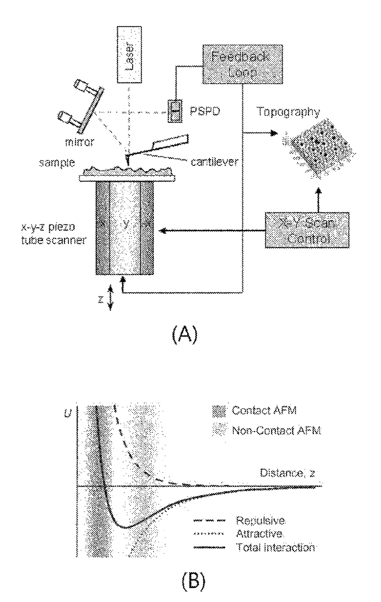
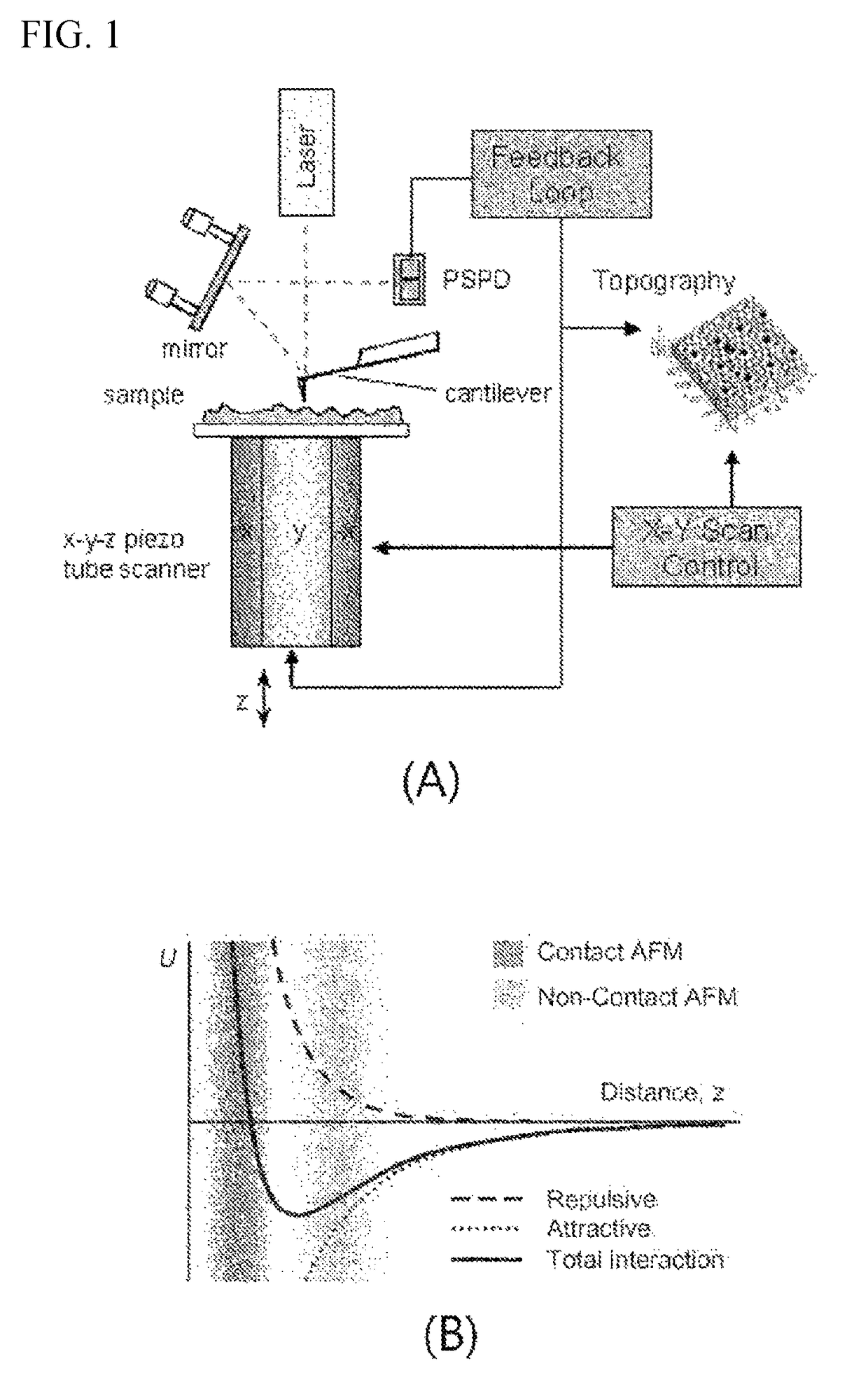
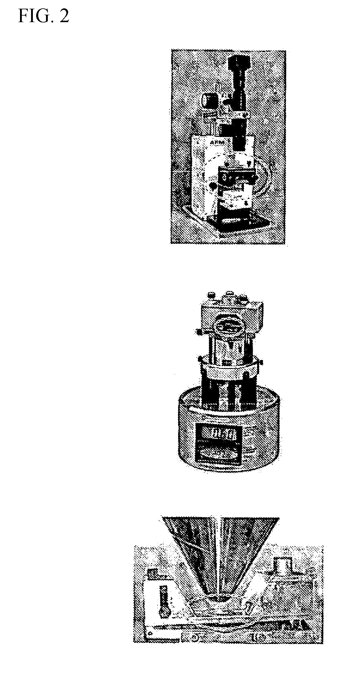
of Main Elements]100: integrated-head for atomic force microscope (according tothe present invention)110: measuring part110a, 110b: through-hole (for coupling between mirror mounts 111and 112 and measuring part 110)111: first mirror mount111a: first mirror mount body part111b: first mirror mount mirrorsupport part111c: first mirror mount fixing111d: first mirror mount anglecoupling holeadjusting screw hole111e: first mirror mount bead groove112: second mirror mount112a: second mirror mount body part 112b: second mirror mountmirror support part112c: second mirror mount fixing 112d: second mirror mountcoupling holeangle adjusting screw hole112e: second mirror mountbead groove115: tip mount115a: tip mount body part115b: tip mount guide groove 115c: tip mount press plate115d: tip mount fixing coupling hole 115e: tip mount guide coupling hole115f: PZT115g: upper insulator plate 115h: lower insulator plate120: source part125: penetrating path130: sensing part135: accommodating pathP: (las...


PUM


Abstract

An object of the application is to provide a head-integrated for an atomic force microscope capable of realizing minimization of a weight and a volume and improvement of structural stability by optimizing a head structure of the atomic force microscope. Another object of the application is to provide a head-integrated atomic force microscope capable of being utilized for imaging a large-area sample by enabling high-rate head scan due to dynamic characteristics improved by mounting the integrated-head described above. Still another object of the application is to provide a composite microscope including a head-integrated atomic force microscope, capable of performing high-rate position search and imaging and performing precise observation of a three-dimensional shape up to an atomic image level in a region of interest by combining the head-integrated atomic force microscope having the improved dynamic characteristics as described above and an electron microscope or an optical microscope with each other.

Description

CROSS-REFERENCE TO RELATED APPLICATIONS[0001]The present application is a U.S. National Phase of International Patent Application Serial No. PCT / KR2015 / 014143, entitled “HEAD-INTEGRATED ATOMIC FORCE MICROSCOPE AND COMPOSITE MICROSCOPE INCLUDING SAME,” filed on Dec. 23, 2015. International Patent Application Serial No. PCT / KR2015 / 014143 claims priority to Korean Patent Application No. 10-2014-0187700, filed on Dec. 24, 2014. The entire contents of each of the above-cited applications are hereby incorporated by reference in their entirety for all purposes.TECHNICAL FIELD[0002]The present invention relates to a head-integrated atomic force microscope and a composite microscope including the same, and more particularly, to a head-integrated atomic force microscope capable of having a high resolution and performing high-rate scan through miniaturization and lightness by forming an atomic force microscope (AFM) head using a three-dimensional integrated body, and a composite microscope inc...

Claims


Application Information

Patent Timeline
Patent Type & Authority Patents(United States)
IPC IPC(8): G01Q60/32
CPCG01Q60/32G01Q20/02G01Q30/02G01Q60/38G01Q30/18G01Q60/00G01Q60/24G01Q60/34Y10S977/852
Inventor KIM, DAL HYUNPARK, BYONG CHONSHIN, CHAE HO
Owner KOREA RES INST OF STANDARDS & SCI
Why Eureka
Try Eureka