
Apparatus for damping flywheel

a technology for damping apparatus and flywheel, which is applied in mechanical apparatus, gearing details, gearing, etc., can solve the problems of generating a torsional exciting force in the engine, deteriorating nvh characteristics including rattles and booming noises, and further increasing the torsional exciting force of the engin

Inactive Publication Date: 2014-02-13
HYUNDAI MOTOR CO LTD
View PDF12 Cites 1 Cited by
  • Summary
  • Abstract
  • Description
  • Claims
  • Application Information

AI Technical Summary

Benefits of technology

The present invention provides a small and lightweight apparatus for damping a flywheel in an engine. This increases the inertia of the flywheel, improves the performance of the vehicle's drivetrain and reduces vibrations in the engine. It also ensures silent and stable drivability and a comfortable ride for the vehicle.

Problems solved by technology

Generally, the driving force is always unbalanced by the change in gas pressure of a piston in an internal combustion engine, thus generating a torsional exciting force in the engine.
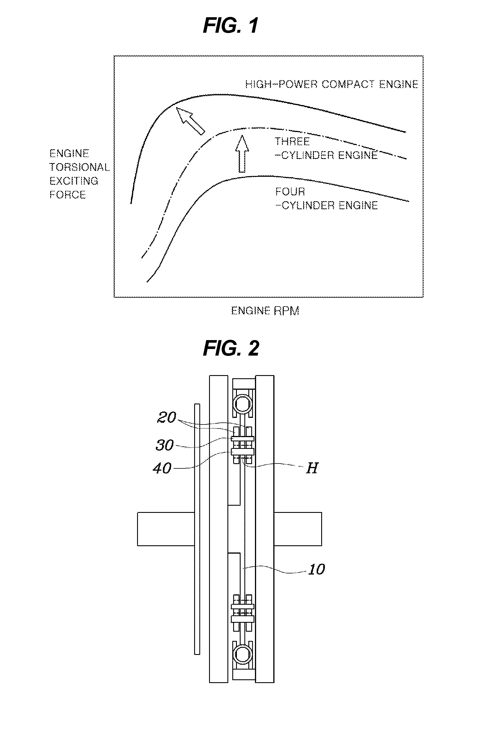
However, as shown in FIG. 1, such an engine is problematic in that the NVH characteristics including rattles and booming noise are deteriorated, as the torsional exciting force of the engine is further increased.
Particularly, as torsional vibrations increase in gear pairs of a gear step in a gearbox, shock and noise are further increased by the rattles.
However, the conventional mass-body installing structure is problematic in that, due to the lack of space, the inertia of the mass body, the length of the flywheel and of the mass body, and the distance from the center of the mass body to the axis of rotation of the flywheel, etc. are restricted, so that the possible increase in the vibration reducing effect that can be achieved using the conventional structure is limited.

Method used


Image

  • Apparatus for damping flywheel
  • Apparatus for damping flywheel
  • Apparatus for damping flywheel

Examples


Embodiment Construction

[0038]Reference will now be made in detail to various embodiments of the present invention(s), examples of which are illustrated in the accompanying drawings and described below. While the invention(s) will be described in conjunction with exemplary embodiments, it will be understood that present description is not intended to limit the invention(s) to those exemplary embodiments. On the contrary, the invention(s) is / are intended to cover not only the exemplary embodiments, but also various alternatives, modifications, equivalents and other embodiments, which may be included within the spirit and scope of the invention as defined by the appended claims.

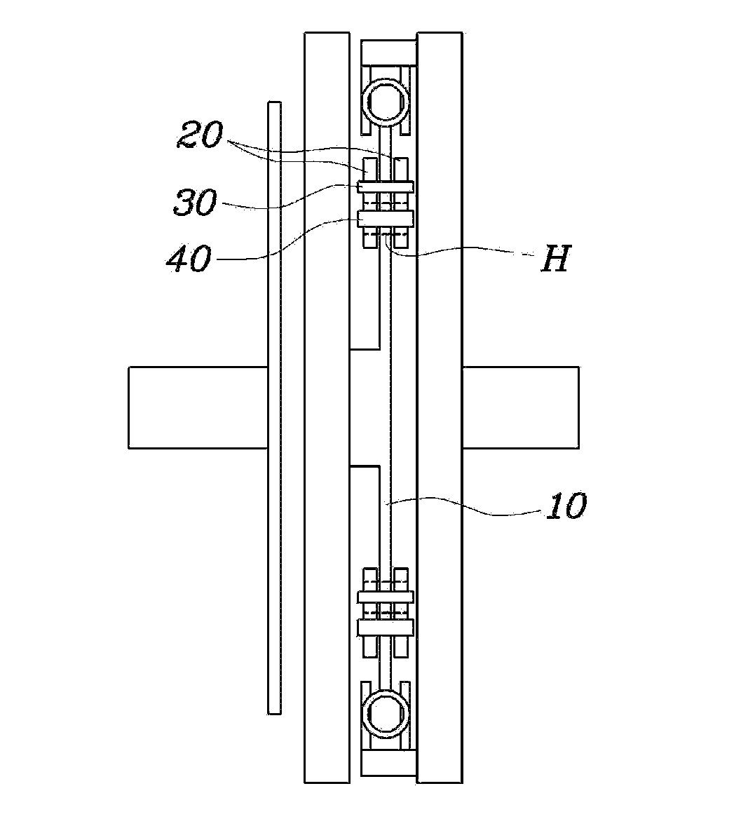
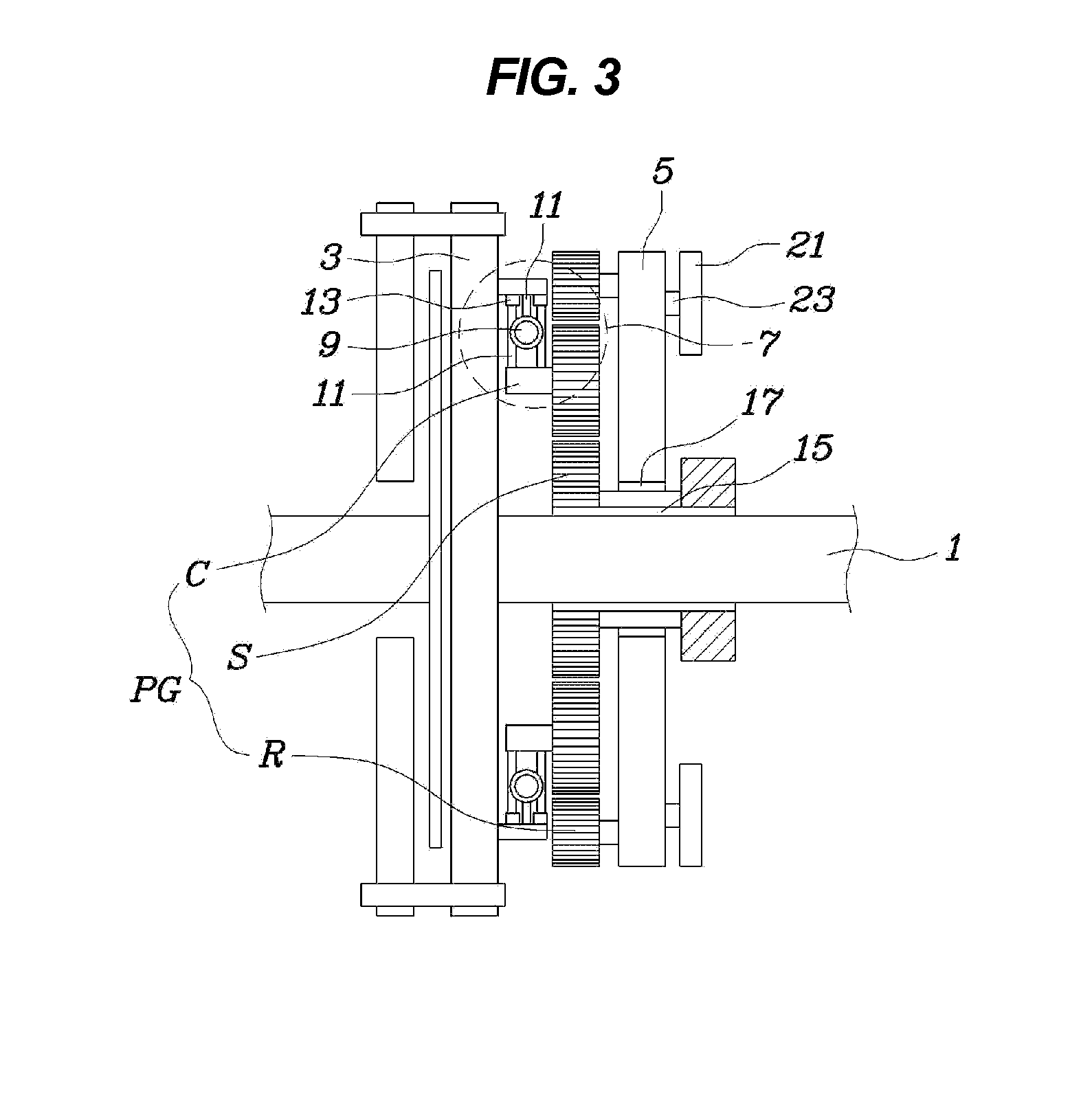
[0039]As shown in FIGS. 3 to 8, a flywheel damping apparatus of the present invention includes a drive plate 3, a flywheel 5, a rigidity imparting means 7, and a mass body 21. The drive plate 3 is integrally connected to a crankshaft 1. One will appreciate that the drive plate may be monolithically formed with the crankshaft. The flyw...


PUM


Abstract

An apparatus for damping a flywheel includes a drive plate integrally connected to a crankshaft A flywheel is connected to receive a rotating force from the drive plate through planetary gearing, and is mounted to rotate relative to the crankshaft. A rigidity imparting means is disposed on a path along which a rotating force is transferred between the drive plate and the flywheel. A mass body is provided on the flywheel, and is configured to perform relative rotation in a direction that offsets a torsional vibration of an engine transmitted to the flywheel.

Description

CROSS-REFERENCE TO RELATED APPLICATION[0001]The present application claims priority of Korean Patent Application Number 10-2012-0087322 filed Aug. 9, 2012, the entire contents of which application is incorporated herein for all purposes by this reference.BACKGROUND OF INVENTION[0002]1. Field of Invention[0003]The present invention relates, in general, to an apparatus for damping a flywheel and, more particularly, to a flywheel damping apparatus, intended to improve noise, vibration and harshness (NVH) characteristics of an engine and vehicle drivetrain through a change in rigidity as well as the inertia of a flywheel.[0004]2. Description of Related Art[0005]Generally, the driving force is always unbalanced by the change in gas pressure of a piston in an internal combustion engine, thus generating a torsional exciting force in the engine. Thus, it is preferable for the transmission of the power of the engine to be as constant as possible while the engine is rotating.[0006]In order to...

Claims


Application Information

Patent Timeline
Patent Type & Authority Applications(United States)
IPC IPC(8): F16F15/30
CPCF16F15/30F16F15/1421F16F15/145F16F15/1478Y10T74/2128F16F15/131F16F15/139F16F15/31F16H3/44
Inventor HWANG, JAE WOONGJIN, YONG WOOKOH, WAN SOOSHIN, SEOK YOUNG
Owner HYUNDAI MOTOR CO LTD
Learn More