Hybrid vehicle control method and hybrid vehicle control device

a hybrid vehicle and control method technology, applied in hybrid vehicles, electrical control, machines/engines, etc., can solve the problems of exhaust performance and combustion stability of internal combustion engines that may deteriorate, and achieve the effect of securing exhaust gas purification performance and suppressing a deterioration of combustion stability and exhaust performance of internal combustion engines

Active Publication Date: 2022-07-07
NISSAN MOTOR CO LTD
View PDF2 Cites 0 Cited by
  • Summary
  • Abstract
  • Description
  • Claims
  • Application Information

AI Technical Summary

Benefits of technology

[0010]As a result, it becomes possible for the hybrid vehicle to supply the evaporative fuel as a reducing agent to the exhaust purification catalytic converter before the internal combustion engine starts up.
[0011]Therefore, the hybrid vehicle is able to suppress a deterioration of combustion stability and exhaust performance of the internal combustion engine caused by the evaporative fuel introduced by means of purging, and to secure exhaust gas purification performance of the exhaust purification catalytic converter when the internal combustion engine starts up (self-sustaining operation).

Problems solved by technology

Therefore, for example, when there are few opportunities for an internal combustion engine mounted in a hybrid vehicle to operate during vehicle travel, a forced purging of the canister will take place during operation of the internal combustion engine, so that the exhaust performance and combustion stability of the internal combustion engine may deteriorate due to the evaporative fuel introduced by means of the purge.

Method used


Image

  • Hybrid vehicle control method and hybrid vehicle control device
  • Hybrid vehicle control method and hybrid vehicle control device
  • Hybrid vehicle control method and hybrid vehicle control device

Examples


first embodiment

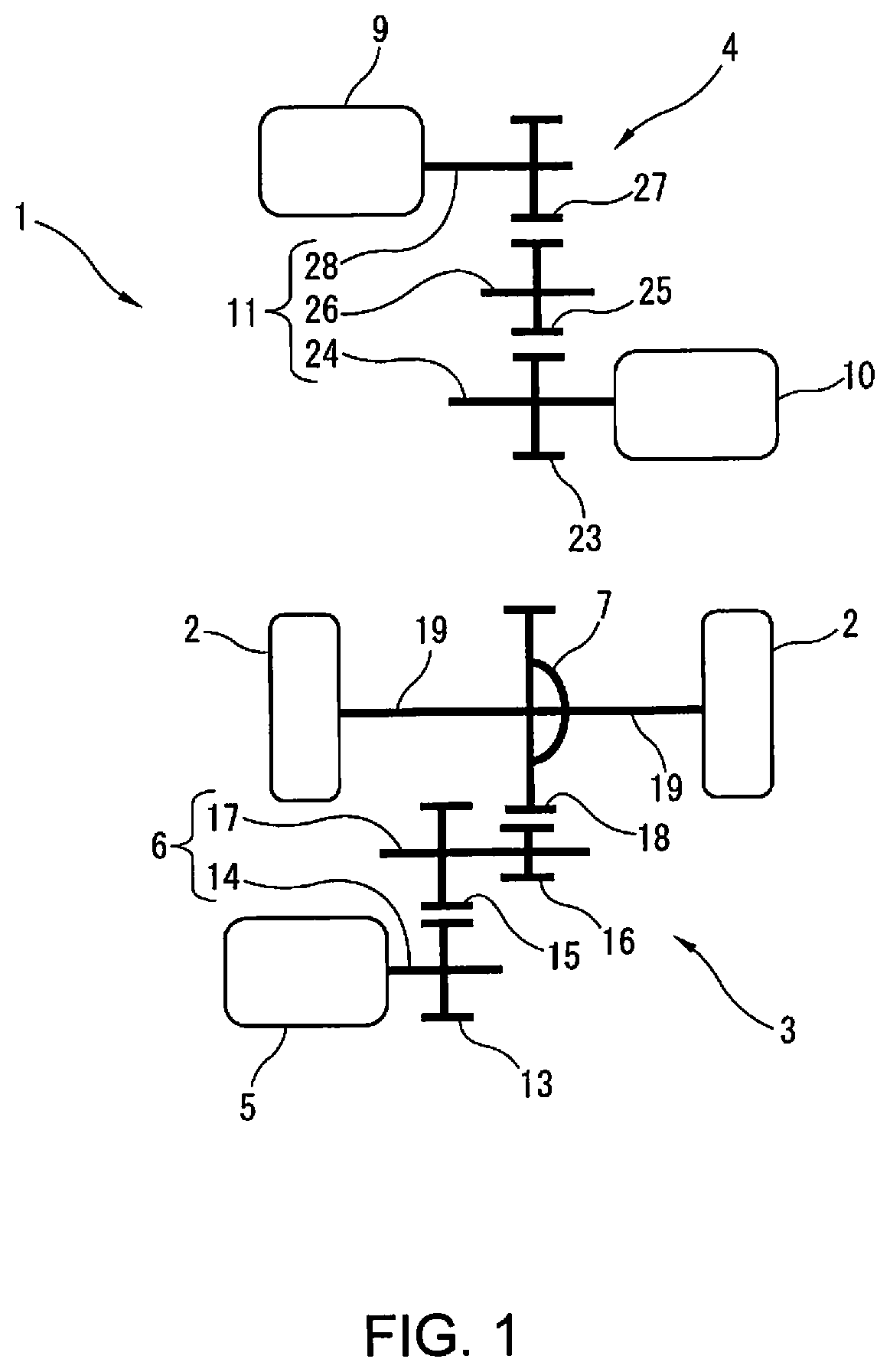
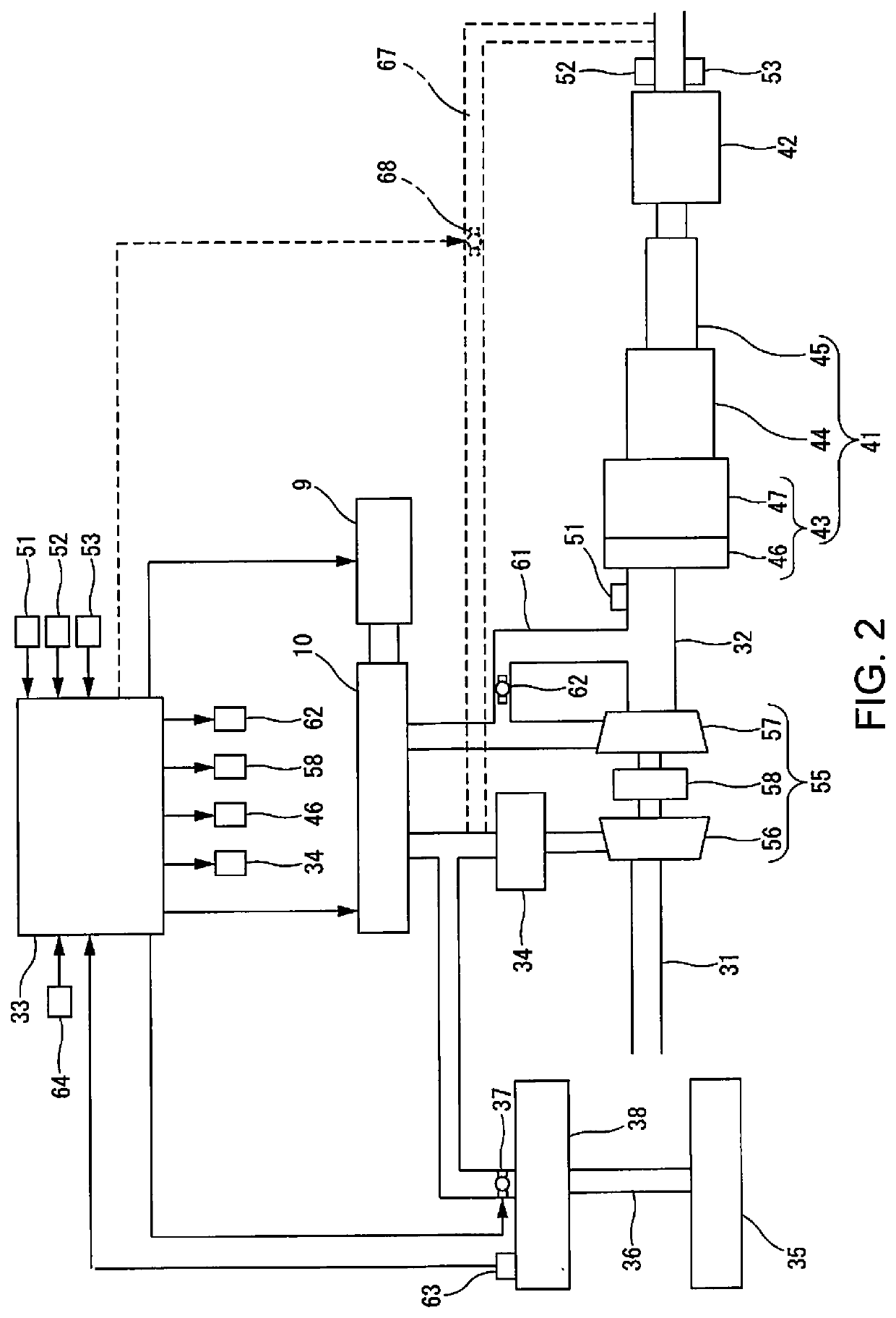
[0021]FIG. 1 is an explanatory diagram schematically illustrating an outline of the drive system of a hybrid vehicle 1 to which the present invention is applied. FIG. 2 is an explanatory diagram schematically illustrating an outline of the system configuration of an internal combustion engine 10 mounted in the hybrid vehicle 1 in the present invention.

[0022]The hybrid vehicle 1 has a drive unit 3 that drives drive wheels 2 and a power generation unit 4 that generates electric power for driving the drive wheels 2.

[0023]The drive unit 3 has a drive motor 5 that rotationally drives the drive wheels 2, and a first gear train 6 and a differential gear 7 that transmit the driving force of the drive motor 5 to the drive wheels 2. The drive motor 5 is supplied with electric power from a not-shown battery charged by the power generated by the power generation unit 4.

[0024]The power generation unit 4 has a generator 9 that can act as an electric motor that generates the power to be supplied t...

second embodiment

[0091]FIG. 4 is a flowchart showing one example of the control flow of the hybrid vehicle 1 of the

[0092]In Step S21, the internal pressure of the canister 38 is detected. In Step S22, it is determined whether the internal combustion engine 10 is stopped. If it is determined in Step S22 that the internal combustion engine 10 is stopped, the process proceeds to Step S23. If it is determined in Step S22 that the internal combustion engine 10 is not stopped, the current routine is ended. In Step S23, the amount of evaporative fuel adsorbed in the canister 38 is estimated from the internal pressure of the canister 38, and it is determined that there is a request for purging the canister 38 when the amount of evaporative fuel is greater than or equal to a prescribed amount set in advance. If there is a purge processing request in Step S23, the process proceeds to Step S24. If there is no purge processing request in Step S23, the current routine is ended. In Step S24, the generator 9 rotat...

third embodiment

[0097]FIG. 5 is a flowchart showing one example of a control flow of the hybrid vehicle 1 in the

[0098]In Step S31, the internal pressure of the canister 38 is detected. In Step S32, it is determined whether the internal combustion engine 10 is stopped. If it is determined in Step S32 that the internal combustion engine 10 is stopped, the process proceeds to Step S33. If it is determined in Step S32 that the internal combustion engine 10 is not stopped, the current routine is ended. In Step S33, the amount of evaporative fuel adsorbed in the canister 38 is estimated from the internal pressure of the canister 38, and it is determined that there is a request for purging the canister 38 when the amount of evaporative fuel is greater than or equal to a prescribed amount set in advance. If there is a purge processing request in Step S33, the process proceeds to Step S34. If there is no purge processing request in Step S33, the current routine is ended. In Step S34, the generator 9 rotates...


PUM


Abstract

A hybrid vehicle includes a canister that adsorbs evaporative fuel generated in the fuel tank for an internal combustion engine. The hybrid vehicle can drive a drive wheel even when the internal combustion engine is stopped. When the internal combustion engine of the hybrid vehicle is stopped and a prescribed set of conditions is satisfied, the internal combustion engine is rotated by the generator. When the internal combustion engine of the hybrid vehicle is rotated by the generator, the evaporative fuel adsorbed in the canister is supplied to the upstream side of an upstream side exhaust catalytic converter device. In the hybrid vehicle, the introduced evaporative fuel as reducing agent is adsorbed in the upstream side exhaust catalytic converter device and a downstream side exhaust catalytic converter device.

Description

CROSS-REFERENCE TO RELATED APPLICATIONS[0001]This application is a U.S. national stage application of International Application No. PCT / IB2019 / 000429, filed on Apr. 19, 2019.BACKGROUNDTechnical Field[0002]The present invention relates to a hybrid vehicle control method and a hybrid vehicle control device.Background Information[0003]Evaporative fuel generated in a fuel tank is adsorbed in a canister mounted in a vehicle. The evaporative fuel adsorbed in the canister is purged and supplied to an internal combustion engine, or the like, when a prescribed set of conditions is satisfied.[0004]For example, in Japanese Laid open application No. 2000-282917 (Patent Document 1), when the operating state shifts from a lean operating region, in which the air-fuel ratio is greater than a theoretical air-fuel ratio, to a rich operating region, in which the air-fuel ratio is below the theoretical air-fuel ratio, the evaporative fuel adsorbed in the canister is introduced into an intake system.[00...

Claims


Application Information

Patent Timeline
Patent Type & Authority Applications(United States)
IPC IPC(8): F02M25/08F02D41/00B60K6/24F01N3/20F02D41/02B60W20/16
CPCF02M25/0836F02D41/0045B60K6/24F01N3/2013F02D41/0275F02D41/042F01N3/2033F02D41/0035B60W20/16F02D2250/24F02M25/089B60W10/06B60K6/46B60W10/08F01N2590/11F01N3/0253F01N13/009F01N3/0814F01N3/101F01N3/2026Y02T10/12Y02A50/20B60W2710/0644
Inventor KIMURA, YOSHIYASU
Owner NISSAN MOTOR CO LTD
Why Eureka
Try Eureka