Dissipative structures and related methods

a technology of dissipative structures and related methods, applied in the direction of shock absorbers, machine supports, mechanical equipment, etc., can solve the problems of ineffective absorption and dissipation of shock pressure, substantial damage, injuries, death, etc., and achieve the effect of absorbing shock pressure and dissipating shock pressur

Inactive Publication Date: 2013-11-05
BATTELLE ENERGY ALLIANCE LLC
View PDF41 Cites 35 Cited by
  • Summary
  • Abstract
  • Description
  • Claims
  • Application Information

AI Technical Summary

Problems solved by technology

Explosive forces and high pressure shock pulses caused by an explosive device or system such as ordnance (e.g., projectiles, bombs, missiles, etc.) or another type of gas or chemical explosion, whether intentional or accidental, may cause substantial damage, injuries, and death.
However, barriers made from concrete take time to construct and once constructed are permanent.
Also, rigid concrete barriers do not absorb or dissipate shock pressure effectively.
As the result of the efficient transmission of the shock pressure pulse, rigid concrete barriers may spall and create harmful flying debris and / or may, in later time, crumble and create damaging falling debris.
Consequently, the use of such liquids requires that the liquid be contained in a desired initial configuration and limits the configuration and application of structures utilizing such a liquid.
The barriers are often bulky which can pose transportation problems and add to the cost of using them and render them undesirable for utilization by a vehicle or by personnel.
Furthermore, the single rows of sealed, discrete container elements only expel the liquid or deformable material into an adjacent volume or element.
The liquid or deformable materials could also be released accidentally by evaporation and expansion of the liquid and gas.

Method used


Image

  • Dissipative structures and related methods
  • Dissipative structures and related methods
  • Dissipative structures and related methods

Examples


Embodiment Construction

[0021]The illustrations presented herein are not meant to be actual views of any particular material, apparatus, system, or method, but are merely idealized representations which are employed to describe embodiments of the present invention. Additionally, elements common between figures may retain the same numerical designation for convenience and clarity.

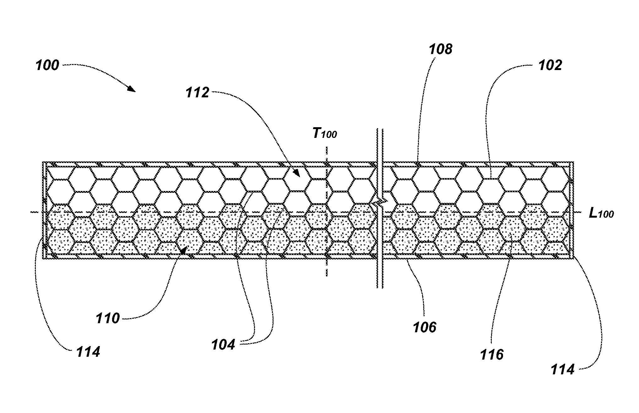
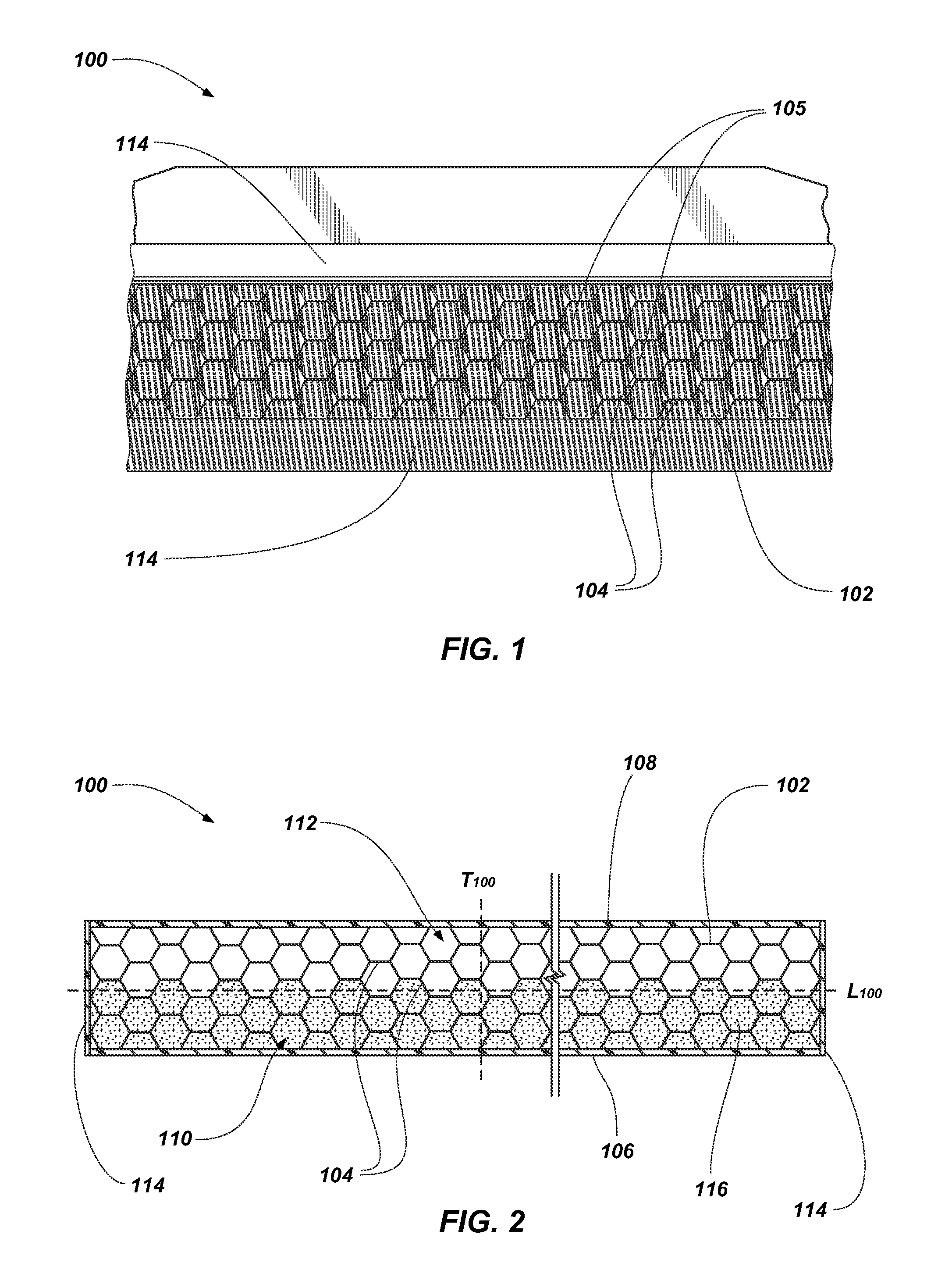
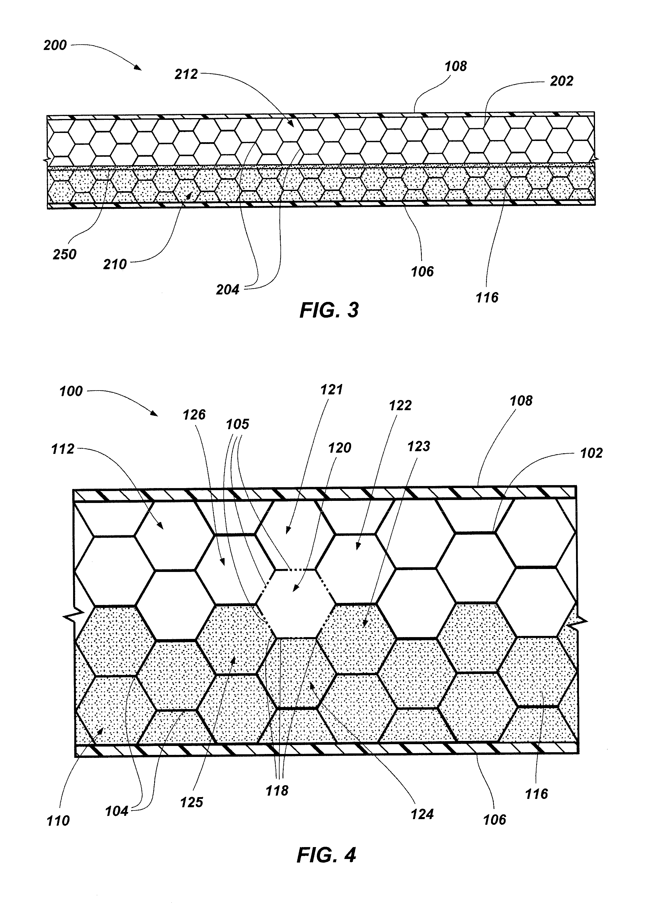
[0022]FIG. 1 illustrates a perspective view of an embodiment of a dissipative structure 100. Referring to FIG. 1, the dissipative structure 100 may include a cell structure 102. The cell structure 102 may include a plurality of interconnected cells 104 disposed between one or more outer layers. The interconnected cells 104 may include apertures 105 extending between the interconnected cells 104. Each interconnected cell 104 may be interconnected to at least one additional cell of interconnected cells 104 through one or more apertures 105. For example, as described in detail below, one cell of the interconnected cells 104 may be con...


PUM


Abstract

Dissipative structures include at least one panel and a cell structure disposed adjacent to the at least one panel having interconnected cells. A deformable material, which may comprise at least one hydrogel, is disposed within at least one interconnected cell proximate to the at least one panel. Dissipative structures may also include a cell structure having interconnected cells formed by wall elements. The wall elements may include a mesh formed by overlapping fibers having apertures formed therebetween. The apertures may form passageways between the interconnected cells. Methods of dissipating a force include disposing at least one hydrogel in a cell structure proximate to at least one panel, applying a force to the at least one panel, and forcing at least a portion of the at least one hydrogel through apertures formed in the cell structure.

Description

STATEMENT REGARDING FEDERALLY SPONSORED RESEARCH OR DEVELOPMENT[0001]This invention was made with government support under Contract No. DE-AC07-051D14517 awarded by the United States Department of Energy. The government has certain rights in the invention.TECHNICAL FIELD[0002]Embodiments of the present invention are directed to dissipative structures for shielding against an applied force. More particularly, embodiments of the present invention are directed to dissipative structures having deformable material disposed within a cell structure in the dissipative structure.BACKGROUND[0003]Explosive forces and high pressure shock pulses caused by an explosive device or system such as ordnance (e.g., projectiles, bombs, missiles, etc.) or another type of gas or chemical explosion, whether intentional or accidental, may cause substantial damage, injuries, and death. Blast dissipative structures are becoming increasingly desired for use in protecting items of value from the effects of such...

Claims


Application Information

Patent Timeline
Patent Type & Authority Patents(United States)
IPC IPC(8): F16F3/02
CPCF16F7/121F16F7/127F16F9/30
Inventor LANGHORST, BENJAMIN R.CHU, HENRY S.
Owner BATTELLE ENERGY ALLIANCE LLC
Why Eureka
Try Eureka