Droplet discharging apparatus, image forming apparatus, and bubble separating method

a technology image forming apparatus, which is applied in the field of droplet discharging apparatus, image forming apparatus, and bubble separation method, can solve the problems of defective discharge operation, difficult replacement of filling fluid with ink, and defected discharge operation, so as to achieve sufficient air storage area and increase fluid substitution efficiency

Inactive Publication Date: 2013-11-05
RICOH KK
View PDF46 Cites 0 Cited by
  • Summary
  • Abstract
  • Description
  • Claims
  • Application Information

AI Technical Summary

Benefits of technology

[0019]A more specific object of the invention may be to increase fluid substitution efficiency while ensuring a sufficient air storing area and without causing a loss of negative-pressure even when a temperature change is caused in the environment.

Problems solved by technology

When the second liquid containing unit or the recording head is filled with the recording fluid, fluid components may coagulate around the nozzles of the recording head during a long storage period, possibly causing a defective discharge operation.
When the second liquid containing unit or the recording head is not filled with the recording fluid, bubbles may remain inside a fluid chamber of the recording head following the initial loading of recording fluid upon arrival of the image forming apparatus, possibly resulting in a defective discharge operation.
However, in a channel structure of the above second liquid containing unit, it is very difficult to substitute the filling fluid with ink when the air storing area of the second liquid containing unit is increased.
Specifically, when the air storing area is large, stagnant areas with reduced flow speed may be present, resulting in a decrease in substitution efficiency.
As a result, the drainage volume required for substitution increases, thus reducing efficiency.
When the air storing area is provided in a negative pressure forming portion within the second liquid containing unit, the contained air may expand due to a change in temperature of the environment, resulting in a loss of the reduced-pressure state within the second liquid containing unit and possibly leading to a leakage of the ink from the head nozzle surface.
However, it has not been easy to completely substitute the filling fluid with ink because the upper portion of the air storing area 101 includes the stagnant area having a low flow speed, which prevents the easy mixing of the filling fluid with ink.
However, this results in an increase in the drainage volume for substituting the filling fluid with ink, resulting in a decrease in efficiency.
Further, because the air storing area 101 is communicated with the fluid storing area 100 including the negative-pressure forming unit, the stored air may expand due to a change in temperature of the environment, resulting in a loss of the reduced-pressure state within the fluid storing area 100 and potentially leading to the leakage of the ink via the head nozzle surface.
Thus, the method according to Patent Document 1 is not capable of easily substituting the filling fluid with ink when the air storing area in the second liquid containing unit is increased.Patent Document 1: Japanese Laid-open Patent Publication No. 2000-94708

Method used


Image

  • Droplet discharging apparatus, image forming apparatus, and bubble separating method
  • Droplet discharging apparatus, image forming apparatus, and bubble separating method
  • Droplet discharging apparatus, image forming apparatus, and bubble separating method

Examples


embodiment 1

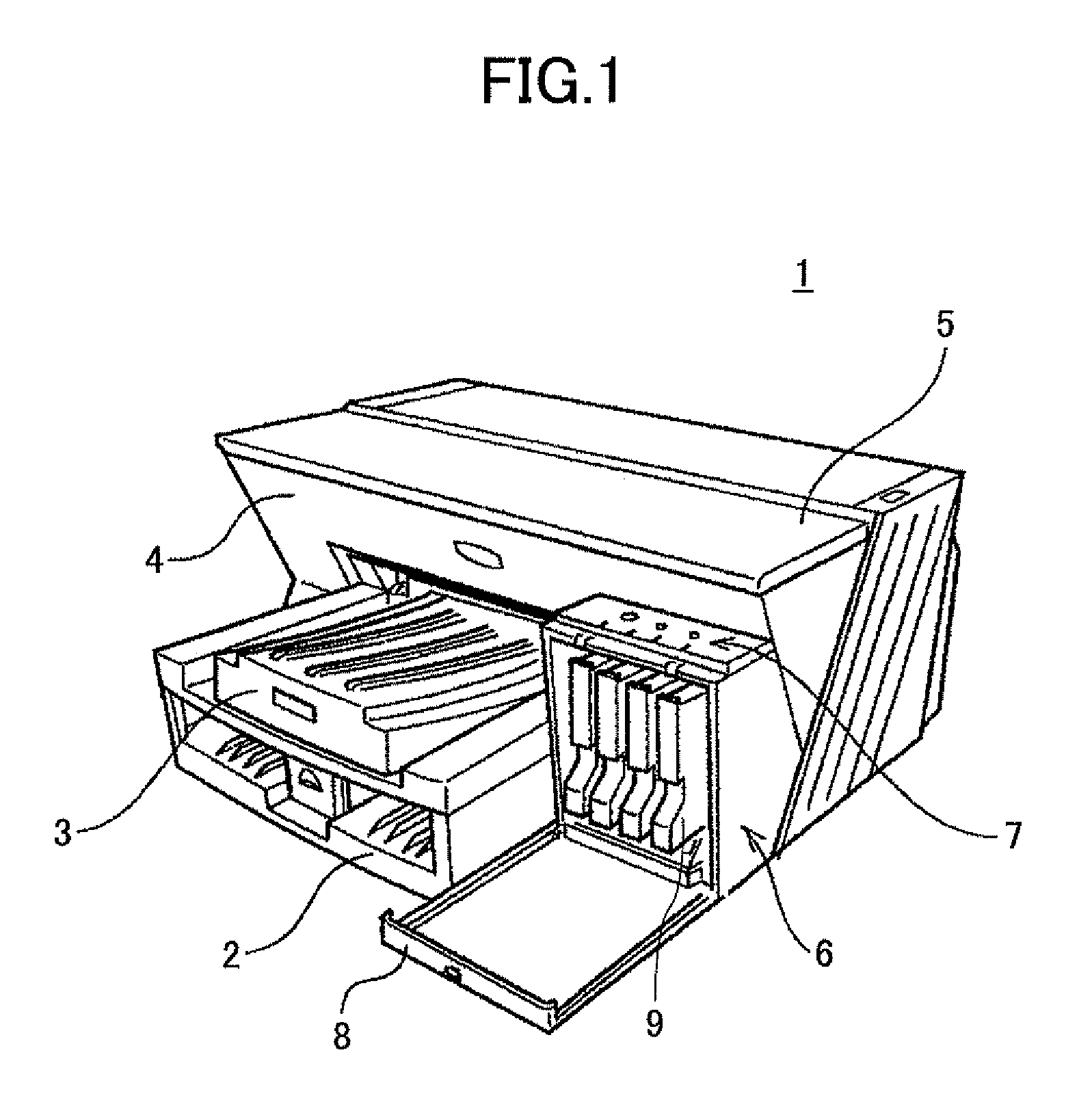
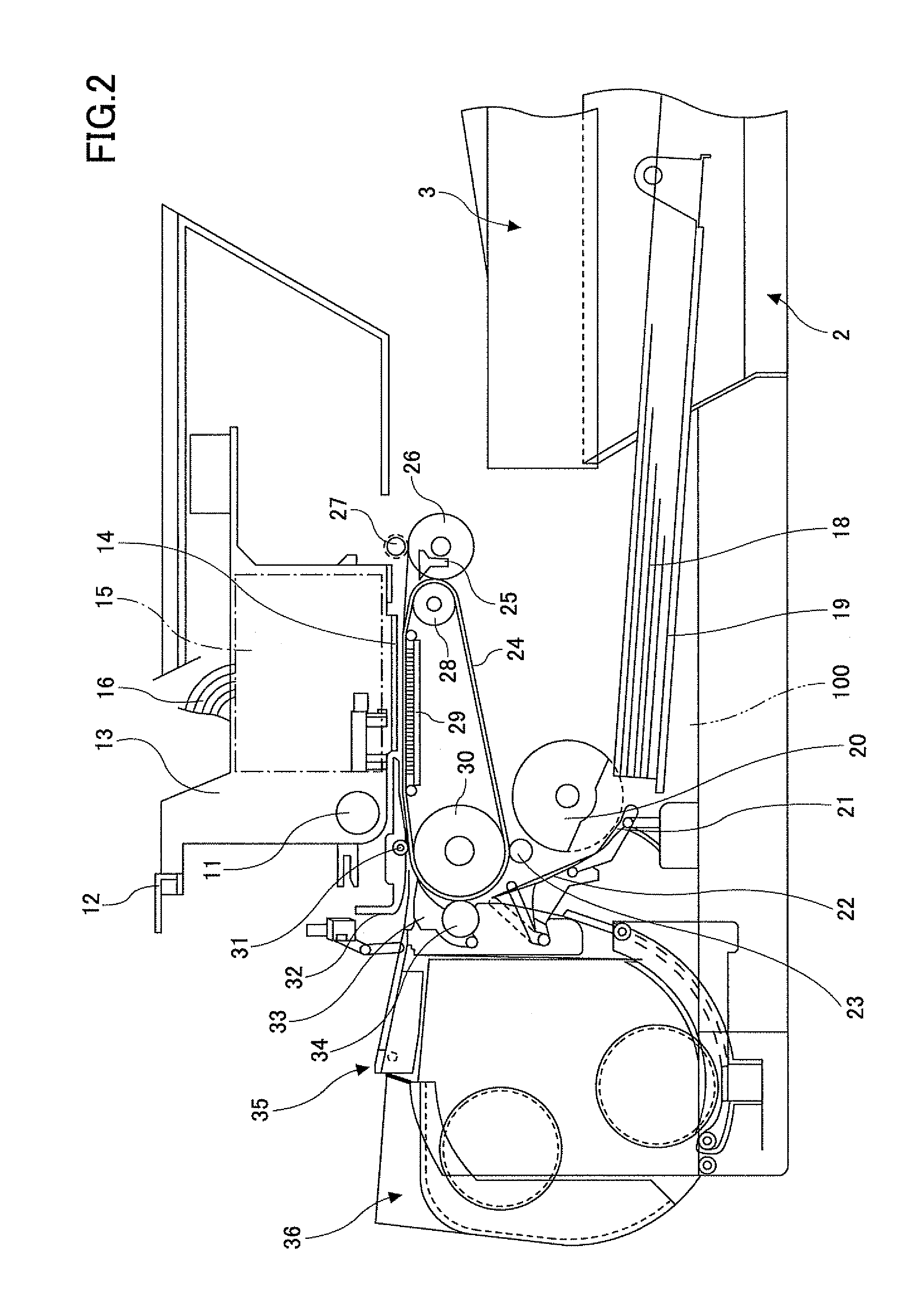
[0036]FIG. 1 is a perspective view of an image forming apparatus 1 according to Embodiment 1. FIG. 2 illustrates a mechanism portion of the image forming apparatus 1. FIG. 3 is a plan view of main portions of the mechanism portion. Referring to FIG. 1, the image forming apparatus 1 includes an apparatus main body 1, a sheet-feeding tray 2 for stocking sheets of a recording material (recording medium), and an ejected-sheet tray 3 for stocking sheets after an image forming operation. The image forming apparatus 1 further includes a (main) ink tank loading unit 6 disposed on one end of a front surface 4 of the apparatus main body 1. On top of the ink tank loading unit 6, an operating unit 7 including operating keys and display units and the like may be disposed. The ink tank loading unit 6 may also include a front cover 8 which may be opened to allow the removal or attaching of a (main) ink tank 9, which may be referred to as a first liquid containing unit.

[0037]As illustrated in FIGS....

embodiment 2

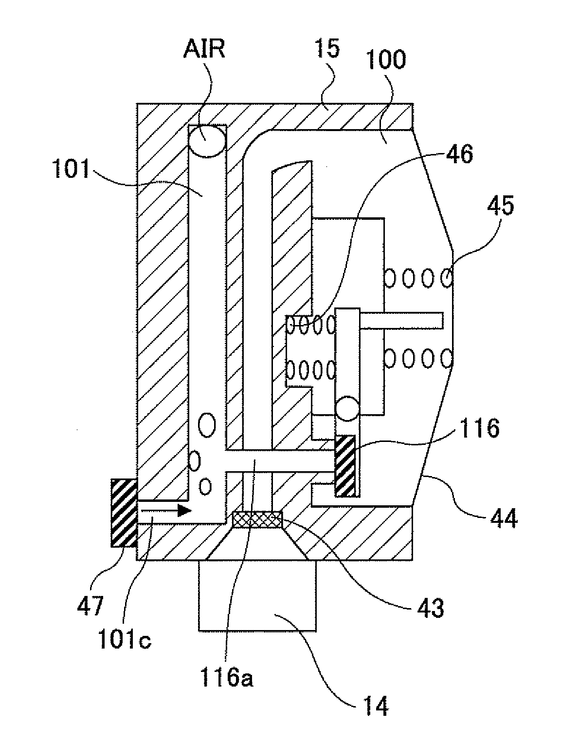
[0060]FIGS. 7A and 7B are a front view and a cross section, respectively, of the sub-tank 15 according to Embodiment 2. The sub-tank 15 according to Embodiment 2 differs from the sub-tank 15 of Embodiment 1 in that the back side of the air storing area 101 is formed by a flexible film 44a.

[0061]By thus forming the back side of the air storing area 101 with the flexible film 44a, an opening area larger than that of the supply channel 16 can be obtained. Further, the volume of the air storing area 101 can be varied temporarily, thus reducing fluid resistance. Thus, the fluid in the air storing area 101 is preferentially caused to flow into the fluid storing area 100, so that the air that may enter the supply channel 16 can be prevented from being discharged into the fluid storing area 100.

[0062]Thus, the sub-tank 15 has a structure that prevents the entry of air into the fluid storing area 100 having the negative-pressure forming unit. As a result, the loss of negative-pressure by th...

embodiment 3

[0064]FIGS. 8A and 8B are a front view and a cross section, respectively, of the sub-tank 15 according to Embodiment 3. The sub-tank 15 according to Embodiment 3 differs from that of Embodiment 1 in that a filter 105 is provided at the boundary between the communicating channel 116a and the air storing area 101, namely, at an inlet portion via which the fluid enters into the communicating channel 116a from the air storing area 101.

[0065]According to the present embodiment, even if bubbles enter into the air storing area 101 together with the fluid from the supply channel 16 when the linked open / close valve 116 is opened upon printing, the flow rate of the fluid is slowed and the bubbles are blocked by the filter 105, thus trapping the bubbles within the air storing area 101. The filter 105 may be made of a material having a small porosity or a small cell density in order to effectively capture small bubbles.

[0066]Thus, the loss of negative-pressure by the expansion of the stored air...


PUM


Abstract

A droplet discharging apparatus for discharging droplets of a recording fluid includes a negative pressure portion and a pressurizing portion connected to the negative pressure portion via a valve. The pressurizing portion is disposed upstream of the valve in a direction of a flow of the recording fluid. The pressurizing portion includes a bubble storing area configured to separate and store bubbles of the recording fluid.

Description

BACKGROUND OF THE INVENTION[0001]1. Field of the Invention[0002]The present invention relates to a droplet discharging apparatus for forming an image by discharging droplets of a recording fluid, an image forming apparatus including the droplet discharging apparatus, and a bubble separating method implemented in the droplet discharging apparatus and the image forming apparatus.[0003]2. Description of the Related Art[0004]Image forming apparatuses include printers, facsimile machines, copy machines, plotters, and multifunction peripherals having multiple image forming functions. As an example of an image forming apparatus of a fluid-discharging recording type, an inkjet recording apparatus is known. In the inkjet recording apparatus, an image is formed (or recorded, transferred, or printed, for example) by discharging droplets of a recording fluid, such as ink, from the recording head onto a recording medium, such as a sheet of paper, as the recording medium is transported. The recor...

Claims


Application Information

Patent Timeline
Patent Type & Authority Patents(United States)
IPC IPC(8): B41J2/19
CPCB41J2/17563B41J2/17596
Inventor NISHIMORI, TAKEHIRO
Owner RICOH KK
Why Eureka
Try Eureka