Film forming method and film forming apparatus

a film forming and film forming technology, applied in the direction of chemical vapor deposition coating, metal material coating process, coating, etc., can solve the problems of limiting the substitution rate of gases, excessive processing gases being purged out, poor control over film thickness, etc., to achieve good control over film thickness and improve gas substitution efficiency

Active Publication Date: 2018-05-08
TOKYO ELECTRON LTD
View PDF12 Cites 0 Cited by
  • Summary
  • Abstract
  • Description
  • Claims
  • Application Information

AI Technical Summary

Benefits of technology

[0009]In view of the above, the present invention provides a film forming method and a film forming apparatus that can ensure good control over film thickness by improving gas substitution efficiency in a processing space when a film is formed by the atomic layer deposition technique.
[0011]Under the circumstances, the present inventors conducted several examinations and have found that, a film can be formed in the ALD mode by increasing the flow rate of a purge gas, in a state where the purge gas is constantly supplied to the processing space and processing gases are sequentially and intermittently supplied, even if the pressure in the processing space is increased. In other words, it has been found that, by increasing the flow rate of the purge gas to a predetermine flow rate or above, good control of film thickness can be achieved in the ALD mode, irrespective of the pressure in the processing space.

Problems solved by technology

When a film is formed by the ALD technique, processing gases are supplied onto a substrate and subsequently excessive processing gases are purged out.
Therefore, it has been considered that control over film thickness becomes poor.
However, if the pressure in the processing space is reduced, a trap for trapping reaction products flowing in an exhaust line limits the substitution rate of gases.
Accordingly, there is a dilemma that the gas substitution efficiency decreases eventually.

Method used


Image

  • Film forming method and film forming apparatus
  • Film forming method and film forming apparatus
  • Film forming method and film forming apparatus

Examples


experimental example

[0067]Next, experimental examples in which the film forming method according to the present invention is actually practiced will be described.

experimental example 1

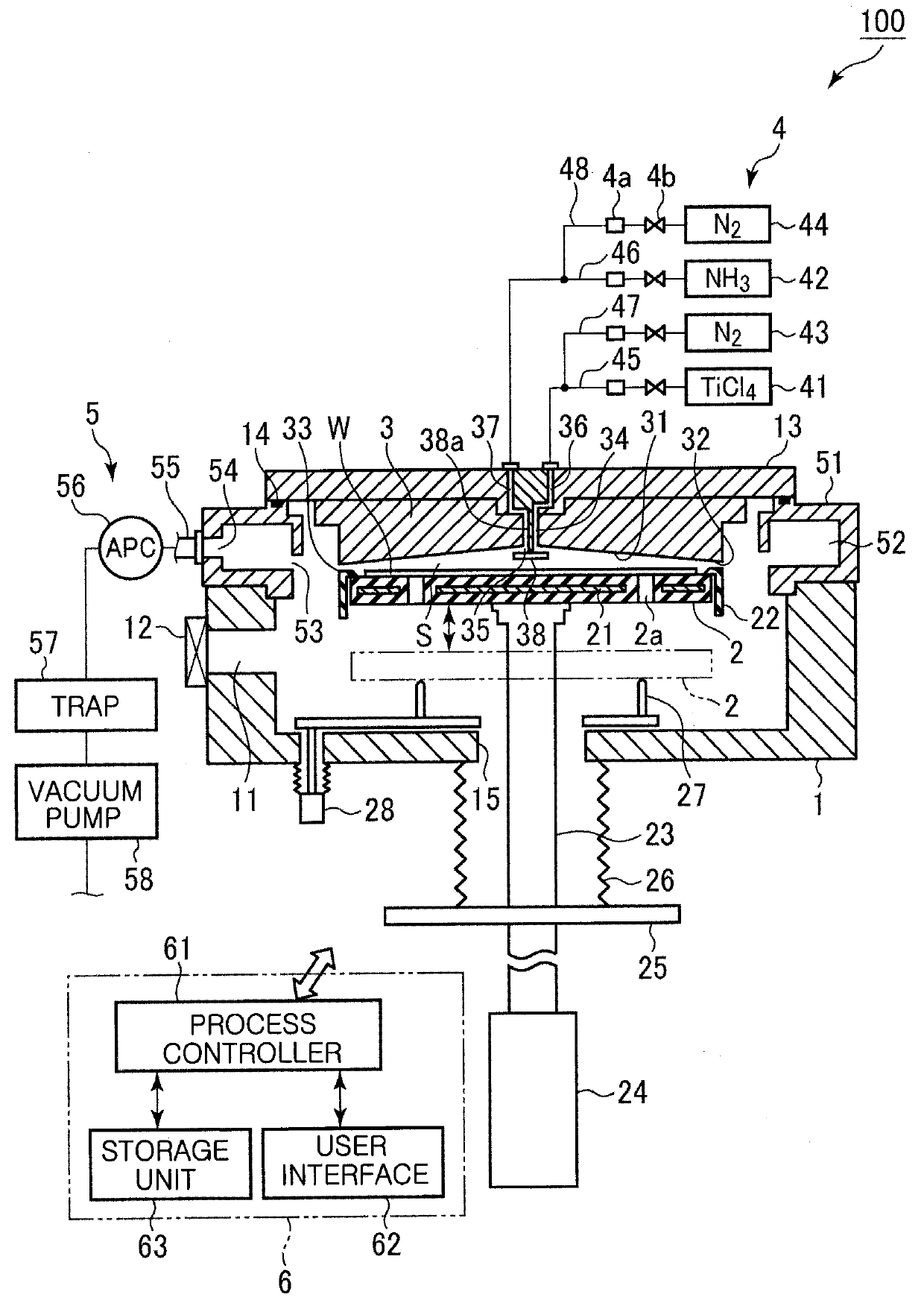
[0068]An apparatus having the configurations illustrated in FIG. 1 with the volume of the processing space of 1,700 mL was used. By using TiCl4 gas and NH3 gas as the processing gases and N2 gas as the purge gas, a TiN film was formed by the ALD technique.

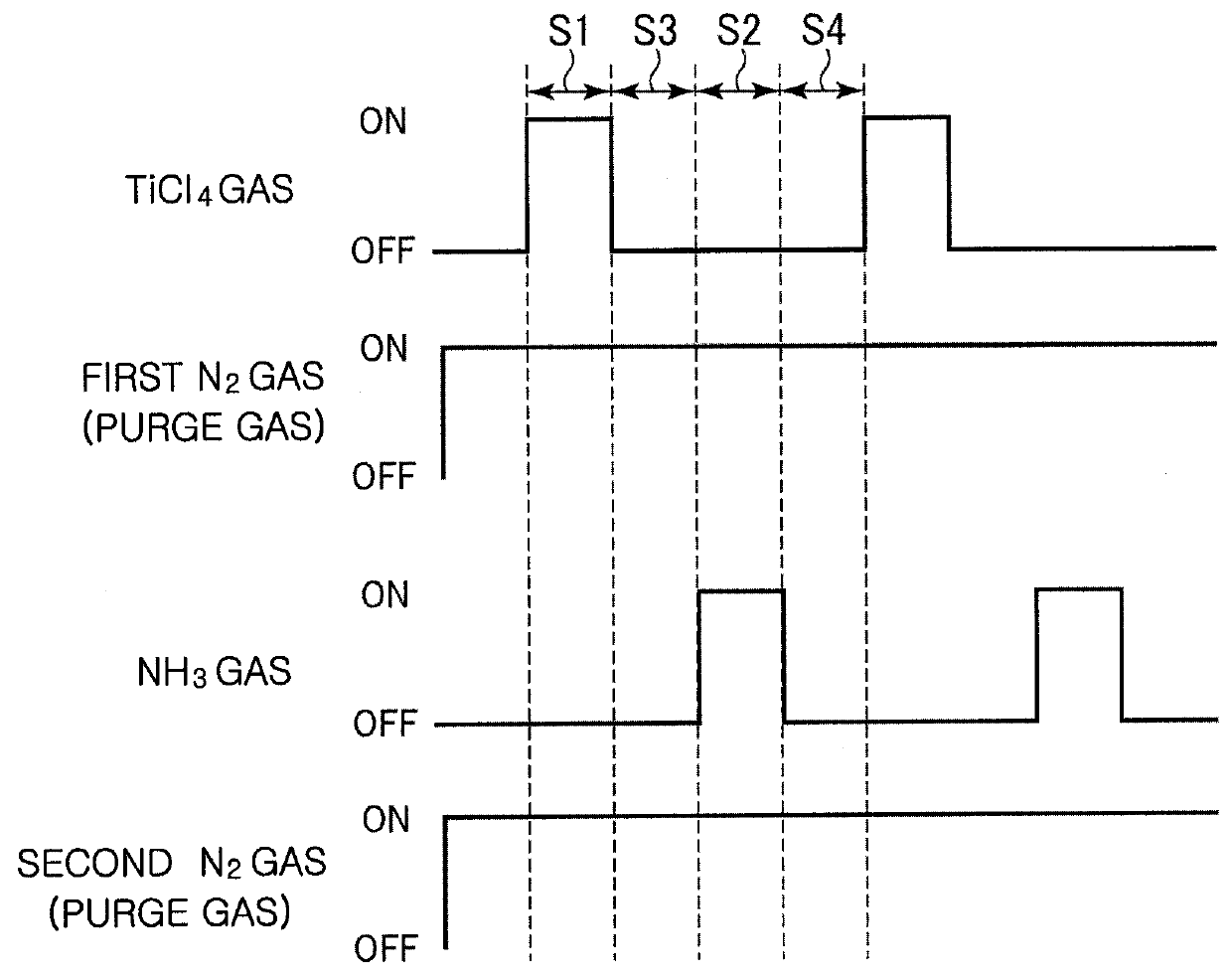
[0069]In this example, operating conditions were set as follows: the mounting table temperature (substrate temperature) of 440° C., the flow rate of TiCl4 gas in one cycle of 50 mL / min (sccm), the flow rate of NH3 gas in one cycle of 2,700 mL / min (sccm), the time period of step S1 of FIG. 3 (TiCl4 gas supplying time) of 0.05 sec, the time period of step S2 (NH3 gas supplying time) of 0.3 sec, and the purge time period of each of steps S3 and S4 of 0.3 sec. The steps S1 to S4 were repeated 315 cycles, varying the pressure in the processing space (the pressure in the processing chamber) between 3 Torr and 7 Torr (between 400 Pa and 933 Pa) and varying the flow rate of N2 gas between 6,000 mL / min and 10,000 mL / min (sccm).

[0070]In this...

experimental example 2

[0074]Next, an apparatus having the configurations illustrated in FIG. 1 with the volume of the processing space of 650 mL was used. By using TiCl4 gas and NH3 gas as the processing gas and N2 gas as the purge gas, a TiN film was formed by the ALD technique.

[0075]In this example, similarly to Experimental Example 1, operating conditions were set as follows: the mounting table temperature (substrate temperature) of 440° C., the flow rate of TiCl4 gas in one cycle of 50 mL / min (sccm), the flow rate of NH3 gas in one cycle of 2,700 mL / min (sccm), the time period of step S1 of FIG. 3 (TiCl4 gas supplying time) of 0.05 sec, the time period of step S2 (NH3 gas supplying time) of 0.3 sec, the purge time of each of steps S3 and S4 of 0.3 sec. The steps S1 to S4 were repeated 315 cycles, varying the pressure in the processing space (the pressure in the processing chamber) between 3 Torr and 7 Torr (between 400 Pa and 933 Pa) and varying the flow rate of N2 gas between 5,000 mL and 9,000 mL (...


PUM

PropertyMeasurementUnit
pressureaaaaaaaaaa
pressureaaaaaaaaaa
pressureaaaaaaaaaa

Abstract

A film forming method includes: forming a thin unit film on a target substrate by supplying processing gases sequentially and intermittently into a processing space, where the target substrate is placed, in a processing chamber of a film forming apparatus while purging the processing gases with a purge gas constantly supplied into the processing space; and repeating the forming of the thin unit film to form a film having a predetermined thickness on the target substrate. A flow rate of the purge gas supplied into the processing space is set such that the film is formed in a film forming mode in which the thin unit film is formed, irrespective of a pressure in the processing chamber.

Description

CROSS-REFERENCE TO RELATED APPLICATIONS[0001]This application claims priority to Japanese Patent Application No. 2013-217327 filed on Oct. 18, 2013, the entire contents of which are incorporated herein by reference.FIELD OF THE INVENTION[0002]The present invention relates to a film forming method and a film forming apparatus.BACKGROUND OF THE INVENTION[0003]In the field of semiconductor device manufacturing, an atomic layer deposition (hereinafter referred to as ALD) attracts attention as a technique to form a certain film on a semiconductor wafer (hereinafter simply referred to as a wafer) which is a substrate.[0004]According to the ALD technique, a film having a desired thickness is formed by repeating plural times an operation of forming a thin unit film, which is almost monomolecular layer. The operation of forming a thin unit film includes: sequentially supplying processing gases (precursors) for forming a desired film into a processing space, where a target substrate is placed...

Claims


Application Information

Patent Timeline
Patent Type & Authority Patents(United States)
IPC IPC(8): C23C16/00C23C16/34C23C16/44C23C16/52C23C16/455
CPCC23C16/52C23C16/34C23C16/45544C23C16/45525C23C16/4412
Inventor ASHIZAWA, HIROAKISATO, MISUZU
Owner TOKYO ELECTRON LTD
Why Eureka
Try Eureka