MRI-room LED lighting system

a led lighting and led light technology, applied in the field of led lighting fixtures and systems, can solve the problems of high magnetic fields which can interfere with other electrical systems, unwanted artifacts, and problems such as problems such as the effect of affecting the operation of the lighting system, and achieve the effect of reducing the cost of the lighting system

Active Publication Date: 2013-11-05
KENALL MFG
View PDF6 Cites 0 Cited by
  • Summary
  • Abstract
  • Description
  • Claims
  • Application Information

AI Technical Summary

Benefits of technology

[0007]An object of the present invention is to provide an LED dimmable lighting system which provides lighting to an MRI room without having the quality of the lighting reduced by the presence of the high magnetic fields in the MRI room.
[0011]An MRI-room LED lighting system having a plurality of LED lighting fixtures and a power supply located outside of the MRI room is provided. The MRI-room LED lighting system includes driver circuitry and PWM dimmer circuitry in each of the lighting fixtures and a dimmer control located outside of the MRI room for controlling the light output of the lighting fixtures. The dimmer control includes variable DC output to control the PWM dimmer circuitry in each lighting fixture such that conductor lines from the power supply and dimmer control do not require electrical shielding to avoid interference between a MRI scanner and the lighting system.
[0012]The conductor lines from the power supply of the MRI-room LED lighting system may be electrically shielded to further reduce frequency interference, including radio frequency interference, on the lines. The conductor lines from the dimmer control of the MRI-room LED lighting system maybe electrically shielded to further reduce frequency interference on the lines.

Problems solved by technology

In environments such as magnetic resonance imaging (MRI) rooms in medical facilities, there can exist high magnetic fields which can interfere with other electrical systems such as the lighting in the room (e.g., light flicker).
It is also the case that equipment such as that found in lighting systems may cause unwanted artifacts (from the radio frequency interference (RFI) emitted by the lighting systems) in the data (corrupted data) being gathered by the MRI system itself.
Both of these effects are problematic in such a facility.
Often the use of dimmer circuitry can be an important source of such interference.

Method used


Image

  • MRI-room LED lighting system
  • MRI-room LED lighting system
  • MRI-room LED lighting system

Examples


Embodiment Construction

briefly described above will be rendered by reference to specific embodiments that are illustrated in the appended drawings. Understanding that these drawings depict only typical embodiments of the invention and are not therefore to be considered to be limiting of its scope, the invention will be described and explained with additional specificity and detail through the use of the accompanying drawings, in which:

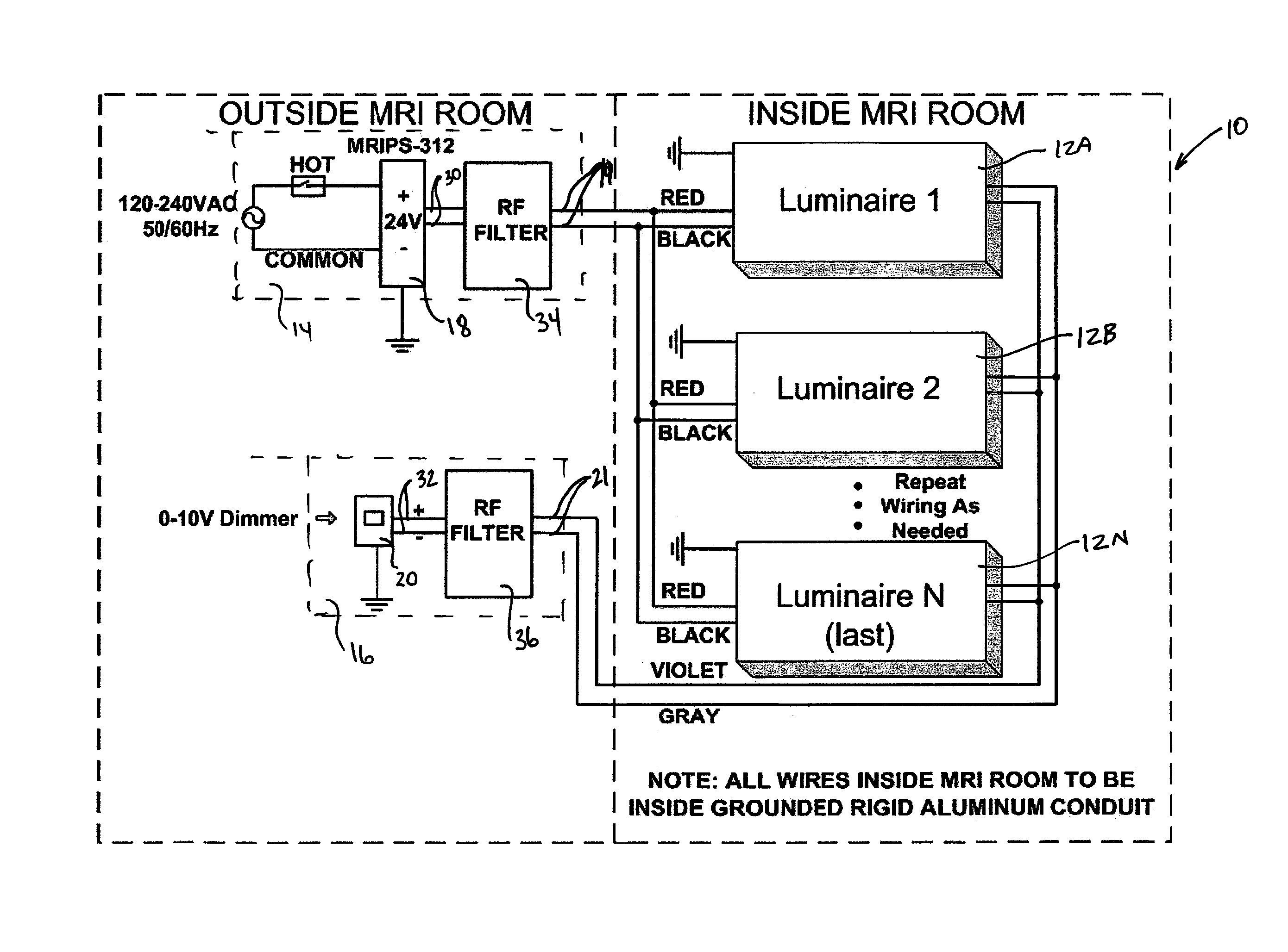
[0015]FIG. 1 is a schematic block diagram of an embodiment of the inventive LED lighting system for MRI rooms.

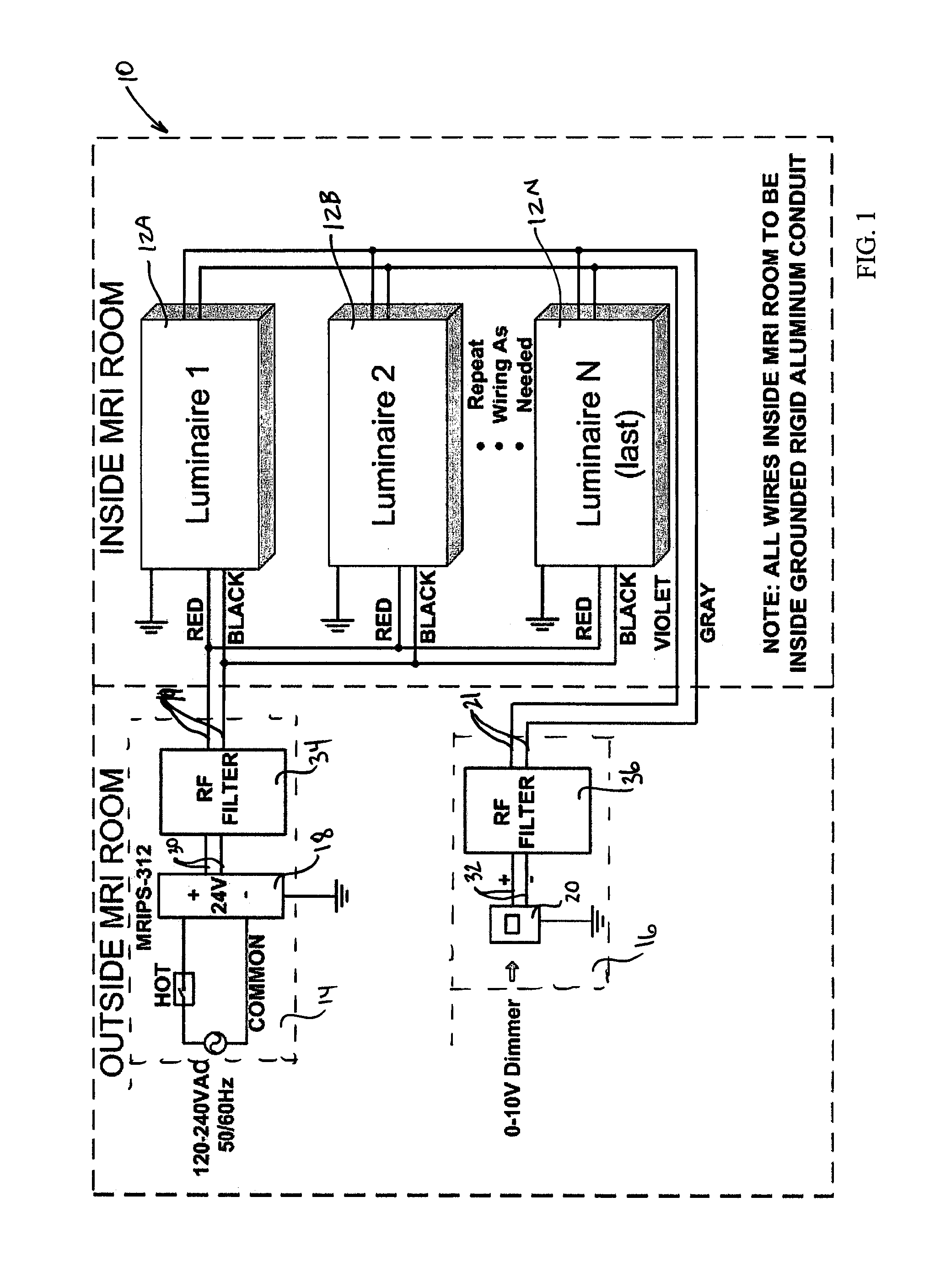
[0016]FIG. 2 is a photograph of a 4-foot by 4-foot ceiling mount, recessed grid graphic image LED lightbox luminaire and a 6-inch aperture recessed LED downlight luminaire, both as used in an embodiment of the inventive LED lighting system of FIG. 1 and installed in a grid ceiling system.

[0017]FIG. 3 is a photograph of a circuit board containing LED's and driver circuitry for a graphic image LED lightbox luminaire.

[0018]FIG. 4 is a photograph of a dimmer circuit usin...


PUM


Abstract

In an MRI-room LED lighting system having a plurality of LED lighting fixtures and a power supply located outside of the MRI room, the improvement comprising: driver circuitry and PWM dimmer circuitry in each of the lighting fixtures and a dimmer control located outside of the MRI room for controlling the light output of the lighting fixtures, the dimmer control having a variable DC output to control the PWM dimmer circuitry in each lighting fixture, whereby conductor lines from the power supply and dimmer control do not require electrical shielding avoid interference between a MRI scanner and the lighting system.

Description

RELATED APPLICATION[0001]This application claims the benefit of U.S. Provisional Application No. 61 / 334,000 filed on May 12, 2010, the contents of which is incorporated by reference herein in its entirety.FIELD OF THE INVENTION[0002]This invention is related generally to lighting technology. More particularly, the invention relates to the field of LED lighting fixtures and systems for use in environments in which there exist high magnetic fields and / or radio frequency interference which can interfere with or be interfered by electrical systems within the environment such as an MRI (magnetic resonance imaging) room.BACKGROUND OF THE INVENTION[0003]In environments such as magnetic resonance imaging (MRI) rooms in medical facilities, there can exist high magnetic fields which can interfere with other electrical systems such as the lighting in the room (e.g., light flicker). It is also the case that equipment such as that found in lighting systems may cause unwanted artifacts (from the ...

Claims


Application Information

Patent Timeline
Patent Type & Authority Patents(United States)
IPC IPC(8): H01J5/02
CPCH05B33/0803H05B33/0818H05B45/325H05B45/395Y02B20/30
Inventor CARTWRIGHT, BRANDON S.
Owner KENALL MFG
Why Eureka
Try Eureka