Navigation system activation of a vehicular directional signal

a technology of navigation system and turn signal, which is applied in the field of navigation system, can solve the problems of compromising affecting the safety of passengers, and the navigation system is still not optimal, so as to prevent the automatic deactivation of the turn signal and promote safety

Active Publication Date: 2013-11-05
TOYOTA MOTOR ENGINEERING & MANUFACTURING NORTH AMERICA
View PDF17 Cites 16 Cited by
  • Summary
  • Abstract
  • Description
  • Claims
  • Application Information

AI Technical Summary

Benefits of technology

[0007]Devices, methods and systems are disclosed herein to describe a signal actuation system. In one embodiment, as the navigation system determines that the vehicle is approaching a turn or other operation which may find it beneficial to signal to other drivers via the turn signals (e.g., lane change, u-turn, and the like) the turn signal may be automatically actuated in the appropriate direction. Once the navigation system determines that it is appropriate to deactivate the turn signal, the turn signal may be automatically deactivated. In this fashion, other drivers on the road may be able to anticipate the actions of the vehicle based on the activation and deactivation of the turn signals, and in turn, accidents may be prevented.
[0013]In yet another embodiment, the physical devices and systems described herein may perform methods that include detecting that a turn signal has been activated, preventing the turn signal from being deactivated until the turn has been completed or the vehicle is past the intersection even if the steering wheel operation would normally have deactivated the turn signal. For example, a driver may activate a turn signal and intend for the turn signal to stay active as the driver moves from a left-most lane to a right-most lane and subsequently exits a freeway (especially when the freeway has 4 or more lanes). However, some vehicles automatically deactivates the turn signal based on steering wheel operation (e.g., moving over one lane and then proceeding straight may cause the turn signal to automatically deactivate and require the driver to reactivate the turn signal if he or she desires) causing inefficiency and possibly encouraging the driver to forego using the turn signal altogether since the driver knows he or she will have to continuously activate the turn signal multiple times as the driver moves from the left-most lane. By using the navigation system to determine the location of the vehicle, the automatic deactivation of the turn signal may be prevented, allowing the driver to continuously signal to other drivers that he / she desires to continue to move lanes and / or turn or exit off a road thereby promoting safety. In one aspect, other features described herein may be modified to incorporate these features.

Problems solved by technology

While sophisticated, and certainly a welcome addition to vehicles, navigation systems are still not optimal.
In this situation, the driver may become frantic and may be focused on what is the quickest way to move over three lanes before the next upcoming exit.
However, since the driver is distracted and focused on shifting the vehicle over to make the exit, the driver may forget to use the turn signals to alert other drivers on the road that the driver is changing lanes or exiting, which in turn, may compromise the safety of passengers and may lead to a car accident.
Even if the driver is able to avoid causing an accident, failure to activate the turn signals may lead to a traffic ticket.
These navigation systems are integrated into the vehicle (e.g., permanently or semi-permanently attached to the central console area and might not be removable for portable use).
However, some vehicles automatically deactivates the turn signal based on steering wheel operation (e.g., moving over one lane and then proceeding straight may cause the turn signal to automatically deactivate and require the driver to reactivate the turn signal if he or she desires) causing inefficiency and possibly encouraging the driver to forego using the turn signal altogether since the driver knows he or she will have to continuously activate the turn signal multiple times as the driver moves from the left-most lane.

Method used


Image

  • Navigation system activation of a vehicular directional signal
  • Navigation system activation of a vehicular directional signal
  • Navigation system activation of a vehicular directional signal

Examples


Embodiment Construction

[0022]Apparatus, systems and methods that implement the embodiments of the various features of the present invention will now be described with reference to the drawings. The drawings and the associated descriptions are provided to illustrate some embodiments of the present invention and not to limit the scope of the present invention. Throughout the drawings, reference numbers are re-used to indicate correspondence between referenced elements.

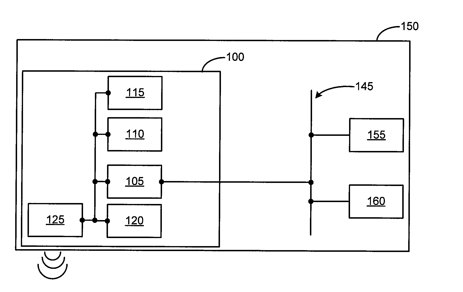
[0023]Turning to FIG. 1, a navigation system 100 as depicted may be connected to the control system of the vehicle 150. In one example, the control system of the vehicle 150 includes a Controller Area Network (CAN) bus 145. The CAN bus 145 is a vehicle bus standard designed to allow microcontrollers and devices to communicate with each other within a vehicle. A modern automobile may have as many as 70 electronic control units (ECU) for various subsystems. For example, ECUs may be used for controlling the turn signals, in addition to other vehi...


PUM


Abstract

Devices, methods and systems describe a turn signal activation system. As the navigation system determines that the vehicle is approaching a turn or other operation, the turn signal may be automatically activated in the appropriate direction (e.g., right-turn signal for a right turn, and a left-turn signal for a left turn). Once the navigation system determines that it is appropriate to deactivate the turn signal, the turn signal may be automatically deactivated. In this fashion, other drivers on the road may be able to anticipate the actions of the vehicle based on the activation and deactivation of the turn signals, and thereby prevent accidents from occurring.

Description

BACKGROUND[0001]1. Field[0002]The present disclosure relates to navigation systems operating in conjunction with motor vehicles, and more particularly relates to methods, devices and systems for automatically activating and deactivating a motor vehicle turn signal.[0003]2. Description of the Related Art[0004]Over the last decade or so, navigation systems, and in particular, those based on a Global Positioning System (GPS), have become popular and extensively used in consumer vehicles and the like. A navigation system that allows a driver to focus on the road without having to look on paper maps while driving, helps prevent a driver from getting lost, and otherwise enhances the driving experience. In typical usage, the driver or another occupant inside the vehicle inputs the destination name or address via an interface (e.g., a LCD screen) on the navigation system. Once the address is ascertained, the navigation system quickly maps out the preferred route and provides instructions ve...

Claims


Application Information

Patent Timeline
Patent Type & Authority Patents(United States)
IPC IPC(8): G01C21/34B60Q1/34B60Q1/40G06F17/40B60Q1/38
CPCB60Q1/34B60Q1/346B60Q1/40G01C21/3661G08G1/09
Inventor WOLTERMAN, MICHAEL J.
Owner TOYOTA MOTOR ENGINEERING & MANUFACTURING NORTH AMERICA
Why Eureka
Try Eureka