System and method for fuel system health monitoring

a fuel system and health monitoring technology, applied in the direction of machines/engines, separation processes, instruments, etc., can solve the problems of engine “no start”, performance deterioration, and loss of accuracy in fuel metering

Inactive Publication Date: 2013-11-12
HAMILTON SUNDSTRAND CORP
View PDF17 Cites 2 Cited by
  • Summary
  • Abstract
  • Description
  • Claims
  • Application Information

AI Technical Summary

Problems solved by technology

Over time, the pump wear results in performance deterioration including reduced flow through the pump and reduced pressure differential across the system.
Reduced flow and reduced pressure differential result in loss of accuracy in fuel metering, and can cause an engine “no start” when pump performance drops below the minimum flow to start an engine to which it supplies fuel.
Such conditions can result in flight delays.
This replacement on fixed intervals, however, can result in pumps being replaced that still have servicable life remaining, or alternatively pumps being replaced long after their accuracy has deteriorated.

Method used


Image

  • System and method for fuel system health monitoring
  • System and method for fuel system health monitoring

Examples


Embodiment Construction

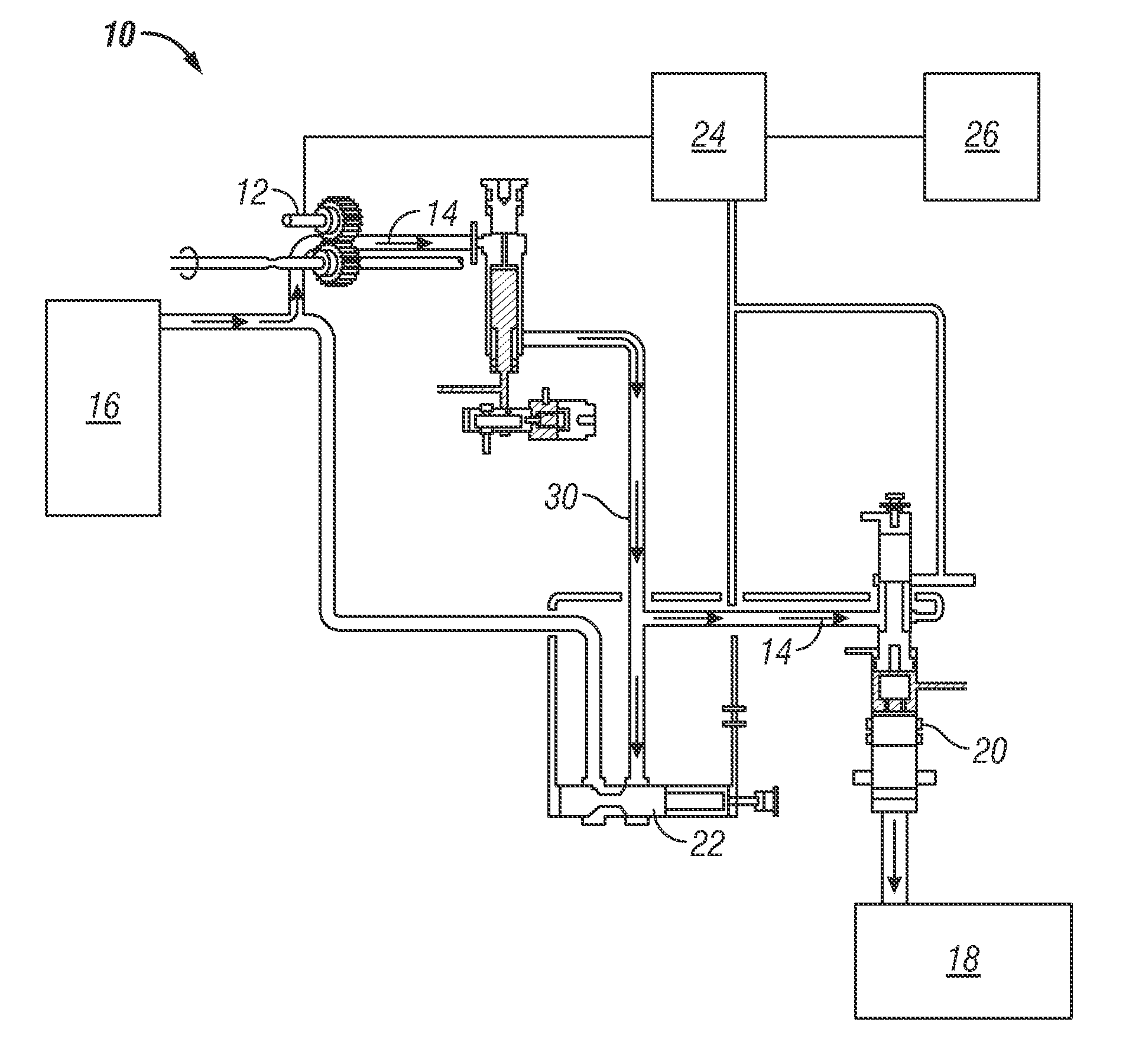
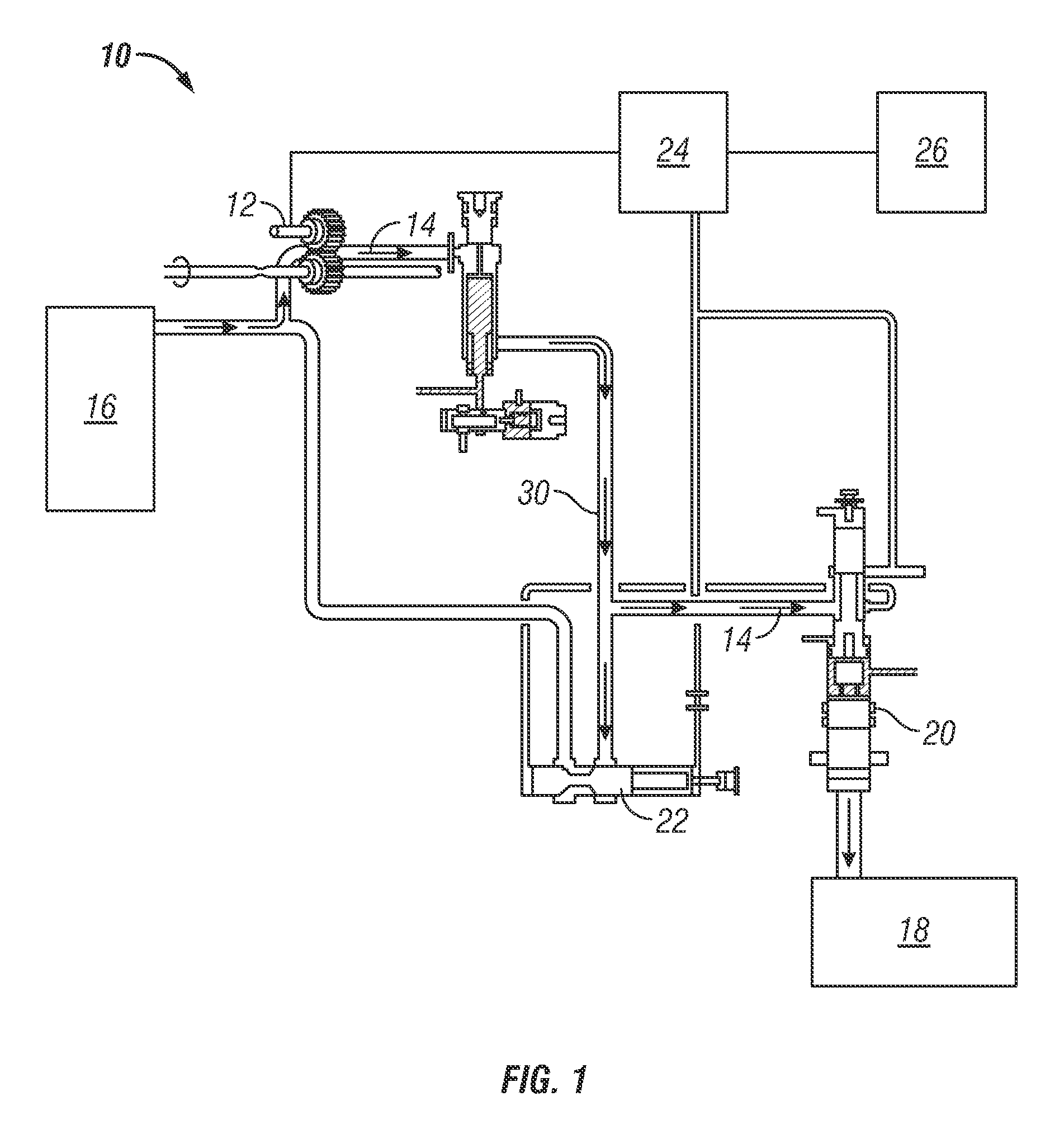
[0009]Shown in the FIGURE is an embodiment of a fuel delivery system 10 for, for example, an aircraft or other vehicle. The system 10 includes a main pump 12 which urges a fuel flow 14 from a fuel source 16, such as a tank or other vessel, toward an engine 18 or other component. In one embodiment, the main pump 12 is a positive displacement pump.

[0010]A metering valve 20 is located between the engine 18 and the main pump 12 to meter the fuel flow 14 to the engine 18. A pressure regulating valve (PRV) 22 is located along a fuel pathway 30 between the main pump 12 and the metering valve 20. The PRV 22 regulates pressure of the fuel flow 14 through the metering valve 20 to a desired level.

[0011]During startup of the engine 18, the PRV 22 and the metering valve 20 are closed until a required fuel system 10 pressure builds up. The pressure is built via operation of the main pump 12 while the valves 20, 22 are closed. When the pressure meets the required fuel system pressure, the PRV 22 a...


PUM

PropertyMeasurementUnit
pressureaaaaaaaaaa
speedaaaaaaaaaa
speedsaaaaaaaaaa

Abstract

A method of monitoring operation of a fuel system includes urging a fuel flow from a fuel source toward a pressure regulating valve via a fuel pump. A pressure of the fuel flow is detected at the pressure regulating valve, and a pump speed required to produce a selected pressure at the pressure regulating valve is detected. The pump speed is compared to a range of acceptable pump speeds, and an operational status of the fuel pump is determined based on a result of the comparison.

Description

BACKGROUND OF THE INVENTION[0001]The subject matter disclosed herein relates to fuel delivery systems. More specifically, the subject matter disclosed herein relates to health monitoring of components of fuel delivery systems.[0002]Fuel delivery systems for an aircraft, for example, include a pump which delivers fuel to a fuel metering valve. Over time, the pump wear results in performance deterioration including reduced flow through the pump and reduced pressure differential across the system. Reduced flow and reduced pressure differential result in loss of accuracy in fuel metering, and can cause an engine “no start” when pump performance drops below the minimum flow to start an engine to which it supplies fuel. Such conditions can result in flight delays. Accordingly, pumps are typically replaced after a predetermined number of hours of operation. This replacement on fixed intervals, however, can result in pumps being replaced that still have servicable life remaining, or alterna...

Claims


Application Information

Patent Timeline
Patent Type & Authority Patents(United States)
IPC IPC(8): G01M15/14G01M15/00
CPCF02M65/00F02C7/22F05D2260/80F05D2260/85Y10T137/86019F02M37/04F02M65/002F05B2260/80G01M13/00
Inventor HEITZ, STEVEN A.POISSON, RICHARD A.
Owner HAMILTON SUNDSTRAND CORP
Why Eureka
Try Eureka