Tank holding mechanism for gas tank and vehicle in which gas tank is mounted using the same

a technology of holding mechanism and gas tank, which is applied in the direction of instruments, signs, transportation items, etc., can solve the problem of not being able to increase the holding force of the bands further

Active Publication Date: 2013-11-12
TOYOTA JIDOSHA KK
View PDF28 Cites 22 Cited by
  • Summary
  • Abstract
  • Description
  • Claims
  • Application Information

AI Technical Summary

Benefits of technology

[0009]In the thus structured tank holding mechanism, the peripheral wall of the cylindrical portion of the gas tank that has been brought into contact with the tank accommodating portion is held by the tank band, and the tank end-side members to which the tank band is secured are provided near respective ends of the gas tank. Therefore, the tank band, which is secured to one of the tank end-side members by the band securing portion, is routed from one of the domical portions toward the cylindrical portion and conforms to the hemispherical outer face of the domical portion. Similarly, the tank band, which is secured to the other tank end-side member, is routed from the other domical portion toward the cylindrical portion and conforms to the hemispherical outer face of the other domical portion. The tank band extends along the diagonal line of the gas tank on the outer face of the cylindrical portion, and conforms to the outer face of the cylindrical portion. The tank band is routed from one of the domical portions through the cylindrical portion to the other domical portion. The thus routed tank band pushes the gas tank against the tank accommodating portion to hold the gas tank. With the thus structured tank holding mechanism that includes the tank band that is looped diagonally across the gas tank, even if an axial force is applied to the gas tank, the axial force may be borne by a portion of the tank band, which conforms to the hemispherical outer face of the domical portion to which the applied force is transmitted. Accordingly, it is possible to more reliably keep holding the gas tank in an appropriate position even if an axial force is applied to the gas tank. If a force directed downward is applied to the outer face of the cylindrical portion, the force may be borne by a portion of the tank band, which extends diagonally across the cylindrical portion and conforms to the outer face of the cylindrical portion. Accordingly, it is also possible to keep holding the gas tank in an appropriate position against the force. In addition, it is possible to keep holding the gas tank in an appropriate position more reliably without excessively increasing the holding force of the tank band. Therefore, it may not be necessary to excessively increase the strength of the tank band, and it may be possible to reduce the cost of the tank band.
[0010]In the tank holding mechanism described above, the tank band may be routed from one of the domical portions through the cylindrical portion to the other domical portion along the direction of fibers that are helically wound around the gas tank, for example, by a filament winding method to reinforce the gas tank. With this arrangement, the tank band may more reliably conforms to the hemispherical outer faces of the domical portions. Therefore, it may be possible to more reliably keep holding the gas tank in an appropriate position even if an axial force is applied to the gas tank.
[0011]In the tank holding mechanism described above, the number of the tank bands may be two. The two tank bands may cross each other on the outer face of the cylindrical portion, and the tank bands may be secured to the tank end-side members by the band securing portions. With this arrangement, it may be possible to more reliably keep holding the gas tank in an appropriate position even if an axial force is applied to the gas tank. In addition, providing two tank bands may not hinder space saving.
[0012]In the tank holding mechanism described above, at least one of the band securing portions positioned at respective ends of the tank band may secure the corresponding end of the tank band to the corresponding tank end-side member while absorbing a force that acts to expand the tank band. With this arrangement, even if the gas tank held by the tank holding mechanism expands or compresses in the radial direction or axial direction of the gas tank, it may be possible to absorb the expansion or compression of the gas tank and keep holding the gas tank in an appropriate position.
[0014]In the vehicle, it is possible to transversely mount the gas tank under a vehicle floor, and keep holding the gas tank in an appropriate position more reliably even if an axial force is applied to the gas tank.

Problems solved by technology

As the wall thickness is reduced, however, it is not possible to further increase the holding force of the bands.

Method used


Image

  • Tank holding mechanism for gas tank and vehicle in which gas tank is mounted using the same
  • Tank holding mechanism for gas tank and vehicle in which gas tank is mounted using the same
  • Tank holding mechanism for gas tank and vehicle in which gas tank is mounted using the same

Examples


Embodiment Construction

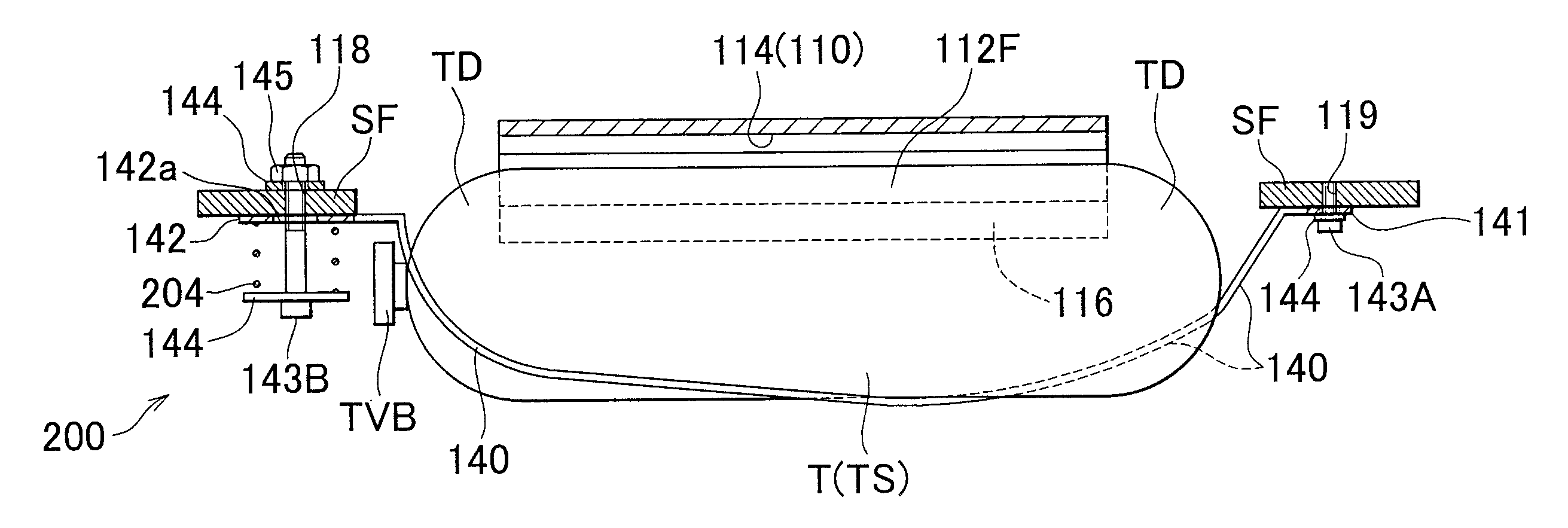
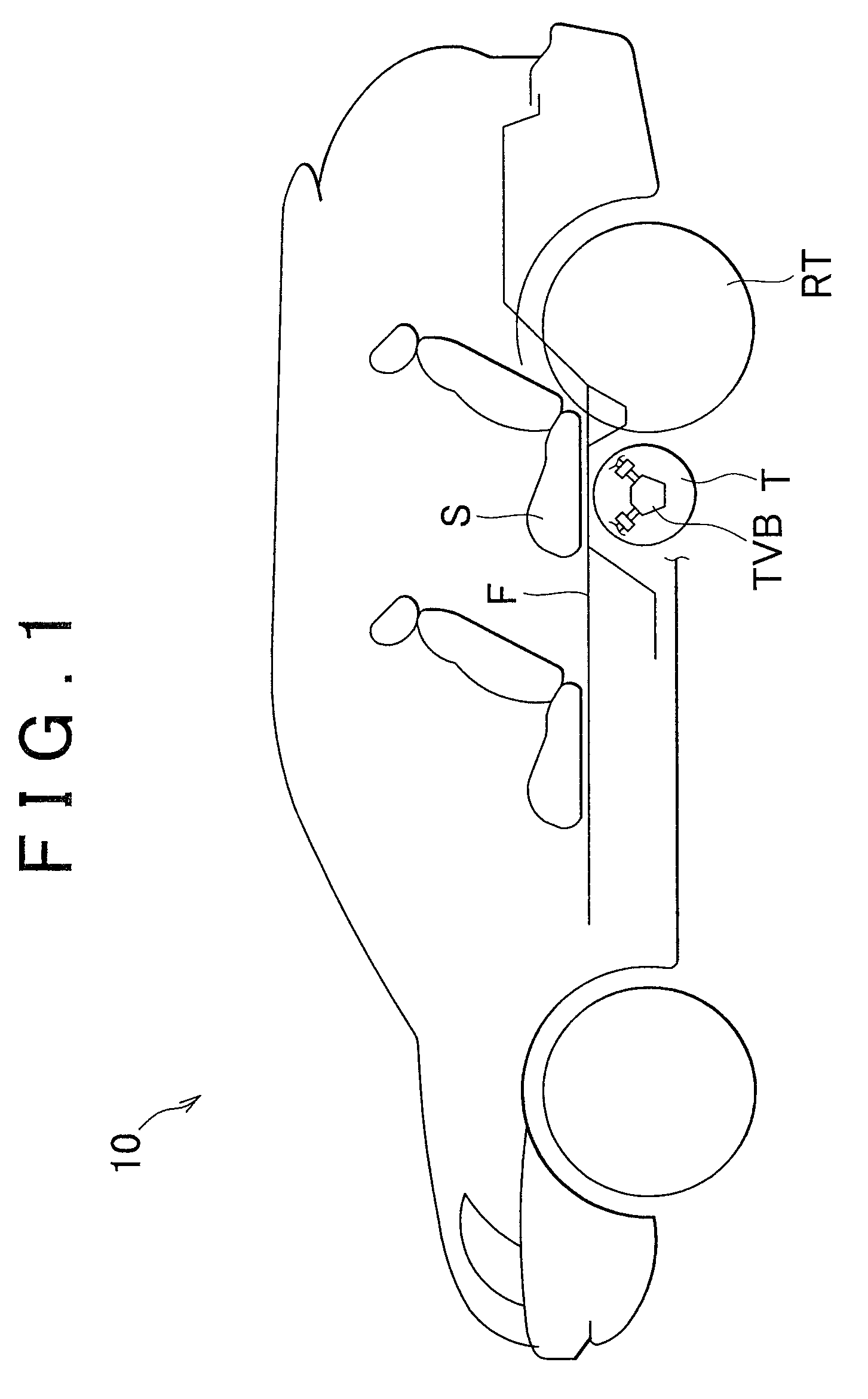
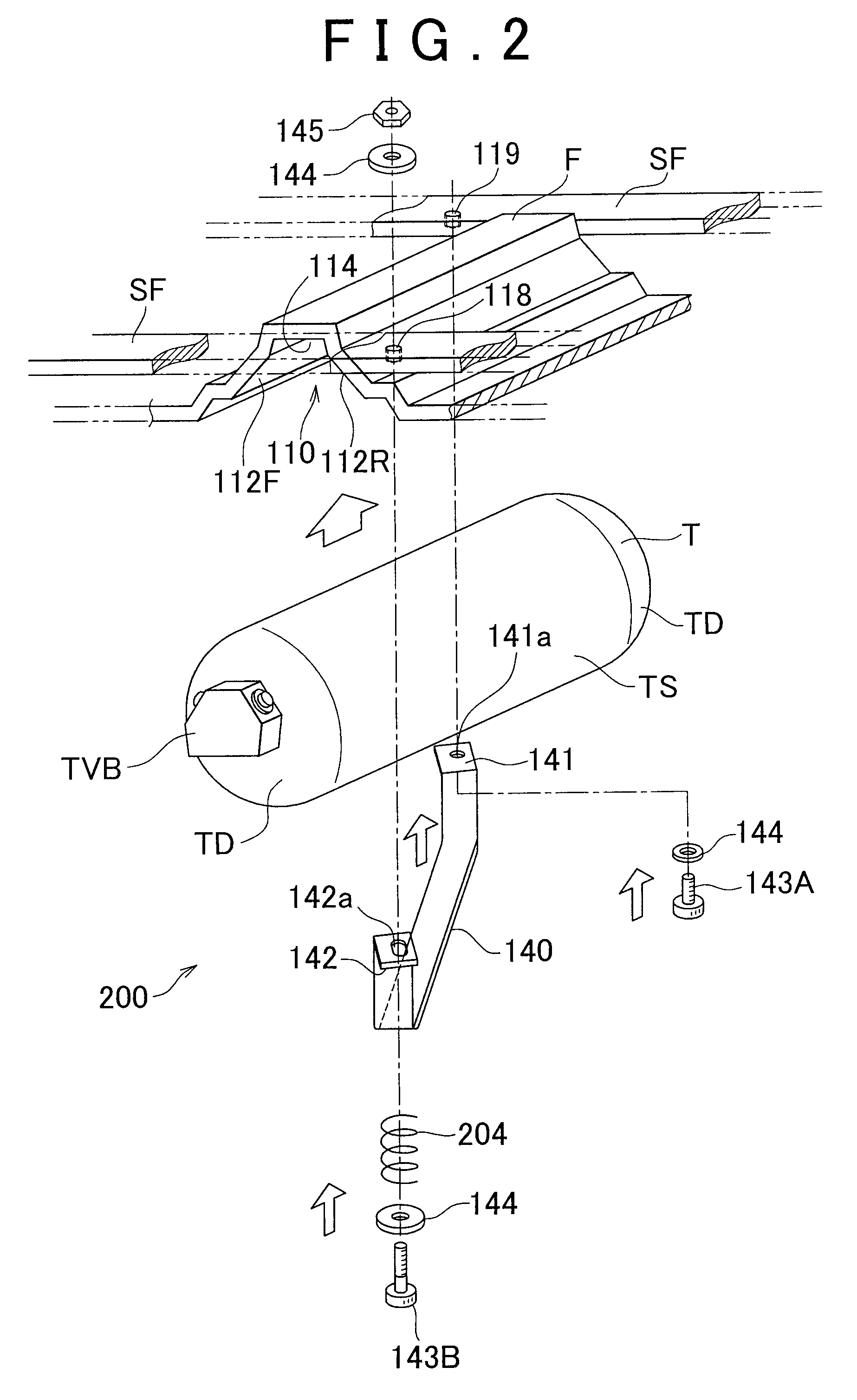
[0026]Hereafter, exemplary embodiments of the invention will be described with reference to the accompanying drawings. FIG. 1 is a view schematically showing the state where a high-pressure gas tank (hereinafter, referred to as “HP gas tank”) T is mounted in a vehicle 10 with the use of a tank holding mechanism according to an embodiment of the invention. FIG. 2 is an exploded view showing the manner in which the HP gas tank T is mounted in the vehicle 10, and showing structures near the HP gas tank T. FIG. 3 is a view schematically showing the positional relationship between the HP gas tank T and a vehicle-side frame near the HP gas tank T along the longitudinal direction of the HP gas tank T. FIG. 4 is a view schematically showing the positional relationship between the HP gas tank T and the vehicle-side frame near the HP gas tank T, viewed from an axial end portion of the HP gas tank T.

[0027]As shown in FIG. 1, in the vehicle 10, the HP gas tank T is transversely mounted under a ...


PUM


Abstract

A tank holding mechanism holds a gas tank that has a cylindrical portion and hemispherical-shaped domical portions formed on respective sides of the cylindrical portion. The tank holding mechanism includes: a tank accommodating portion that contacts a peripheral wall of the cylindrical portion of the gas tank; tank end-side members provided near respective ends of the gas tank; a tank band that pushes the gas tank against the tank accommodating portion; and band securing portions that secure end portions of the tank band to the respective tank end-side members. The tank band is routed from one of the domical portions through the cylindrical portion to the other domical portion. The tank band extends along a diagonal line of the gas tank over an outer face of the cylindrical portion, conforms to the outer face of the cylindrical portion, and conforms to hemispherical outer faces of both of the domical portions.

Description

INCORPORATION BY REFERENCE[0001]The disclosure of Japanese Patent Application No. 2010-008849 filed on Jan. 19, 2010 including the specification, drawings and abstract is incorporated herein by reference in its entirety.BACKGROUND OF THE INVENTION[0002]1. Field of the Invention[0003]The invention relates to a tank holding mechanism that holds a gas tank, and a vehicle in which a gas tank is mounted using the same.[0004]2. Description of the Related Art[0005]In recent years, mounting a high-pressure gas tank (hereinafter, referred to as “HP gas tank”) in a vehicle has become increasingly common. For example, Japanese Patent Application Publication No. 2003-291666 (JP-A-2003-291666) describes a fuel-cell vehicle provided with a HP gas tank that stores hydrogen gas used as fuel gas for a fuel cell. The HP gas tank is transversely mounted in the vehicle.[0006]According to JP-A-2003-291666, multiple bands are wound around a cylindrical portion of the HP gas tank to hold the HP gas tank. ...

Claims


Application Information

Patent Timeline
Patent Type & Authority Patents(United States)
IPC IPC(8): B60K15/067
CPCB60K15/07H01M8/04201B60K2015/0633B60K2015/0634Y02E60/50
Inventor HAYASHI, HIDETSUGUINAGI, SHUSUKE
Owner TOYOTA JIDOSHA KK
Why Eureka
Try Eureka