Supercharge Your Innovation With Domain-Expert AI Agents!

Fan biasing transmission mechanism

a transmission mechanism and fan technology, applied in the direction of rotors, chairs, vessel construction, etc., can solve the problems of large housing size, high cost, complicated structure and high cost,

Active Publication Date: 2013-11-12
TSAI CHING LANG
View PDF6 Cites 0 Cited by
  • Summary
  • Abstract
  • Description
  • Claims
  • Application Information

AI Technical Summary

Benefits of technology

[0005]The present invention has been accomplished under the circumstances in view. It is one object of the present invention to provide a fan biasing transmission mechanism, which can be controlled for enabling the fan body to be biased alternatively forwards and backwards (upwards and downwards) during 360° rotation of the fan motor.

Problems solved by technology

This arrangement has drawbacks: 1. Big size housing; 2. Complicated structure and high cost; 3. Installation and maintenance inconvenience; 4. Being suitable for use in a ceiling fan but not practical for use in a floor fan.

Method used


Image

  • Fan biasing transmission mechanism
  • Fan biasing transmission mechanism
  • Fan biasing transmission mechanism

Examples


Embodiment Construction

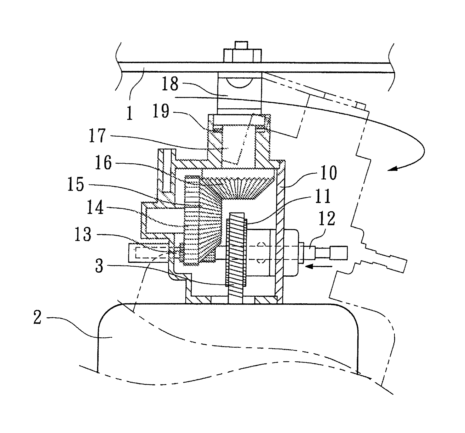
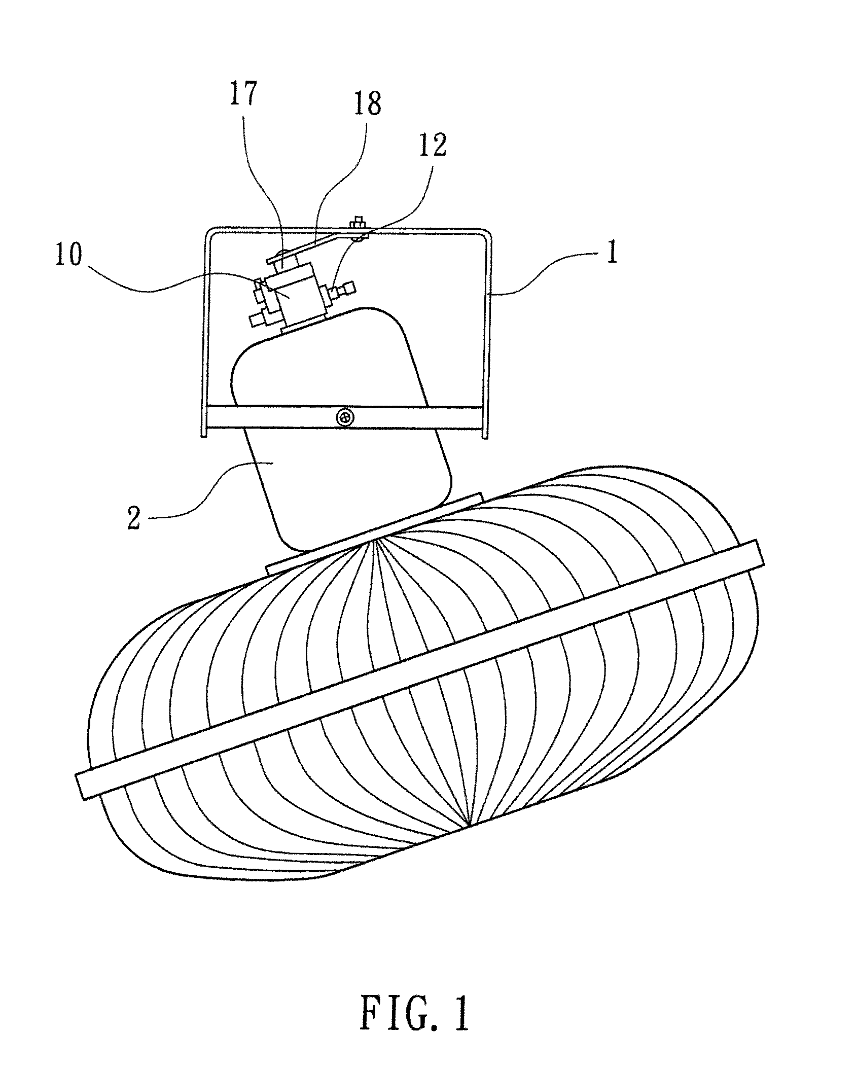
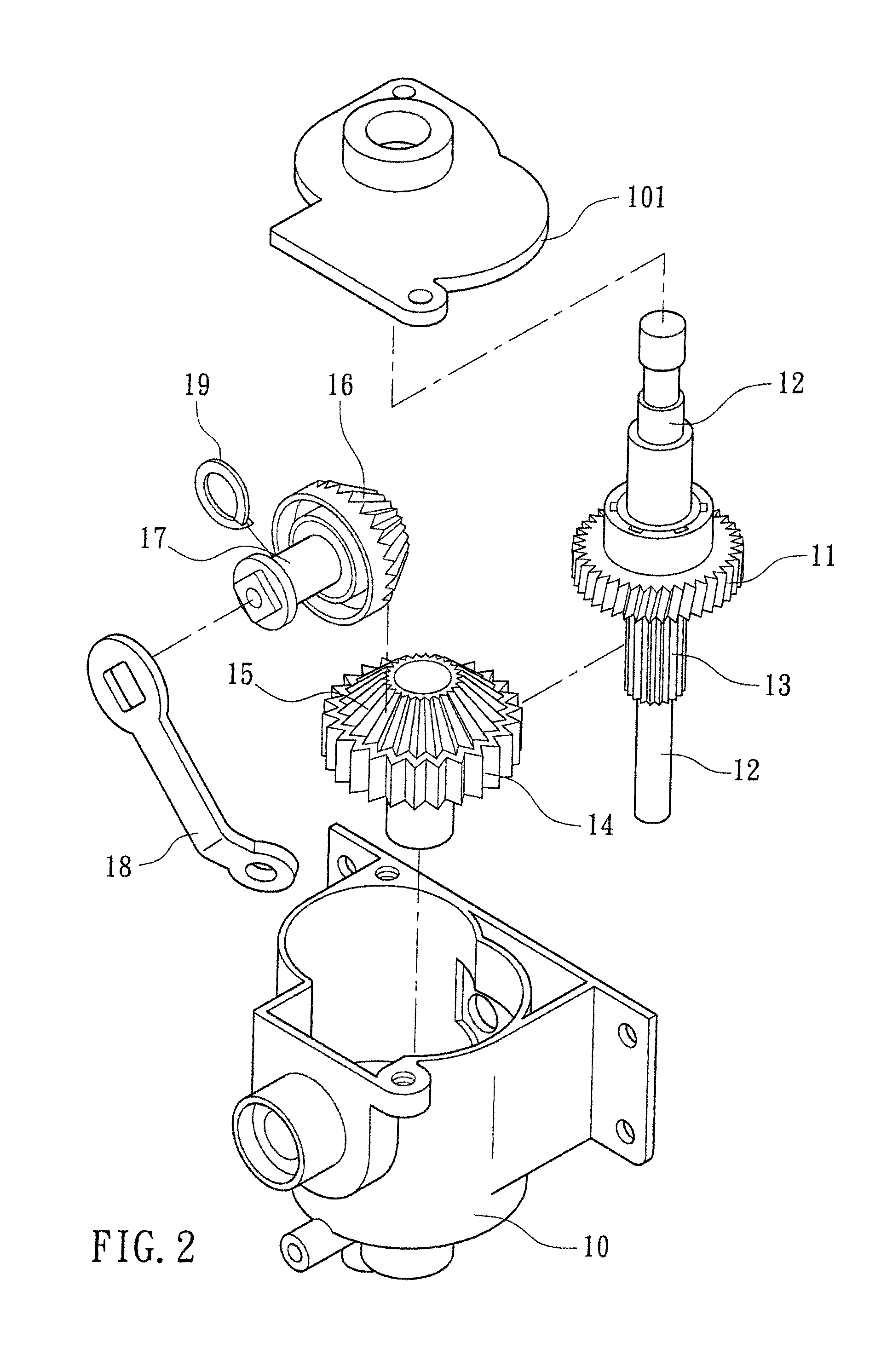
[0013]Referring to FIGS. 1˜5, a fan biasing transmission mechanism in accordance with the present invention is shown comprising a gearbox 10 affixed to the rear side of the housing of an electric fan's fan motor 2, a control rod 12 pivotally and axially movably mounted in the gearbox 10, a power gear 11 fixedly mounted on the control rod 12 and meshed with a motor shaft worm wheel 3 of the fan motor 2 for synchronous rotation with the fan motor 2, a driving gear 14 pivotally mounted in the gearbox 10, a gear-clutch gear 13 fixedly mounted on the control rod 12 and movable with the control rod 12 into mesh with the driving gear 14, a first bevel gear 15 fixedly mounted on the driving gear 14, a second bevel gear 16 meshed with the first bevel gear 15 and having a gear shaft 17, a crank arm 18 pivotally coupled between the gear shaft 17 and a bracket 1, an elastic member 19 connected between the gear shaft 17 and the gearbox 10 to enhance engagement between the first bevel gear 15 and...


PUM


Abstract

A fan biasing transmission mechanism includes gearbox affixed to the rear side of the housing of an electric fan's fan motor, a control rod pivotally and axially movably mounted in the gearbox. a power gear fixedly mounted on the control rod and meshed with a motor shaft worm wheel of the fan motor, a driving gear pivotally mounted in the gearbox, a gear-clutch gear fixedly mounted on the control rod and movable with the control rod into mesh with the gear-clutch gear, a first bevel gear fixedly mounted on the driving gear, a second bevel gear meshed with the first bevel gear, a bracket, a crank arm pivotally coupled between the gear shaft and the bracket, and an elastic member connected between the gear shaft and the gearbox.

Description

BACKGROUND OF THE INVENTION[0001]1. Field of the Invention[0002]The present invention relates to electric fans and more particularly, to a fan biasing transmission mechanism, which can be controlled for enabling the fan body to be biased alternatively forwards and backwards (upwards and downwards) during its 360° rotation.[0003]2. Description of the Related Art[0004]There are commercial electric fans that allow biasing of the fan body during its 360° rotation. In these prior art designs, the mechanism which enables the fan body to be biased during rotation of the fan motor is mounted inside the motor housing. This arrangement has drawbacks: 1. Big size housing; 2. Complicated structure and high cost; 3. Installation and maintenance inconvenience; 4. Being suitable for use in a ceiling fan but not practical for use in a floor fan.SUMMARY OF THE INVENTION[0005]The present invention has been accomplished under the circumstances in view. It is one object of the present invention to prov...

Claims


Application Information

Patent Timeline
Patent Type & Authority Patents(United States)
IPC IPC(8): F01D25/00
CPCF04D25/088F04D25/105
Inventor PAN, JYE-LIANG
Owner TSAI CHING LANG
Features
  • R&D
  • Intellectual Property
  • Life Sciences
  • Materials
  • Tech Scout
  • Unparalleled Data Quality
  • Higher Quality Content
  • 60% Fewer Hallucinations
Learn More