Supercharge Your Innovation With Domain-Expert AI Agents!

Optical position detecting device and display device with position detecting function

a technology of optical position detecting and display device, which is applied in the direction of optical radiation measurement, counting objects on conveyors, instruments, etc., can solve the problems of limited use and deterioration of detection accuracy, and achieve the effect of high accuracy

Inactive Publication Date: 2013-11-12
COLUMBIA PEAK VENTURES LLC
View PDF23 Cites 3 Cited by
  • Summary
  • Abstract
  • Description
  • Claims
  • Application Information

AI Technical Summary

Benefits of technology

This configuration enables high-accuracy detection of the target object's position, including coordinates, by compensating for varying reflection rates and environmental light influences, without requiring the object to be a light-emitting indicating device.

Problems solved by technology

However, in the case of the technique of using the light emitted from the indicating device, since input through a finger, hand or the like is not possible, its usage is limited.
However, in the method shown in FIG. 14, in a case where there exist portions having different reflection rates on the surface of the target object Ob, for example, in a case where there is a partial color difference or gloss difference on the target object Ob, even though the target object Ob is disposed in the same position, the detection intensity in the light detector 30 is changed, thereby deteriorating the detection accuracy.

Method used


Image

  • Optical position detecting device and display device with position detecting function
  • Optical position detecting device and display device with position detecting function
  • Optical position detecting device and display device with position detecting function

Examples


first embodiment

Overall Configuration of Optical Position Detecting Device

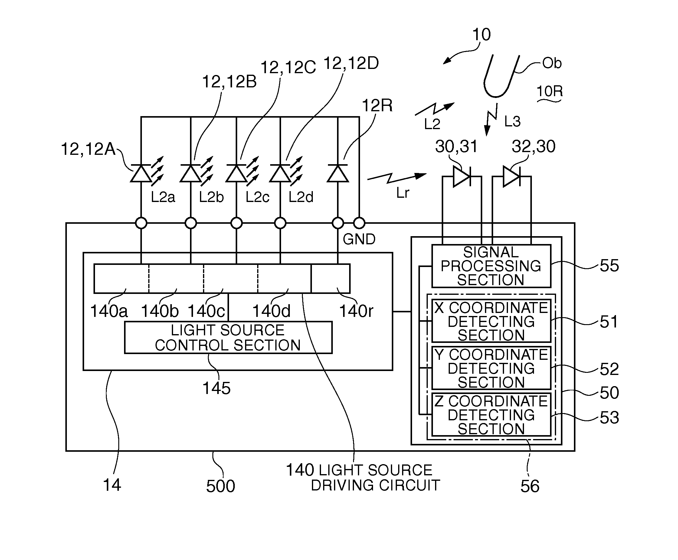
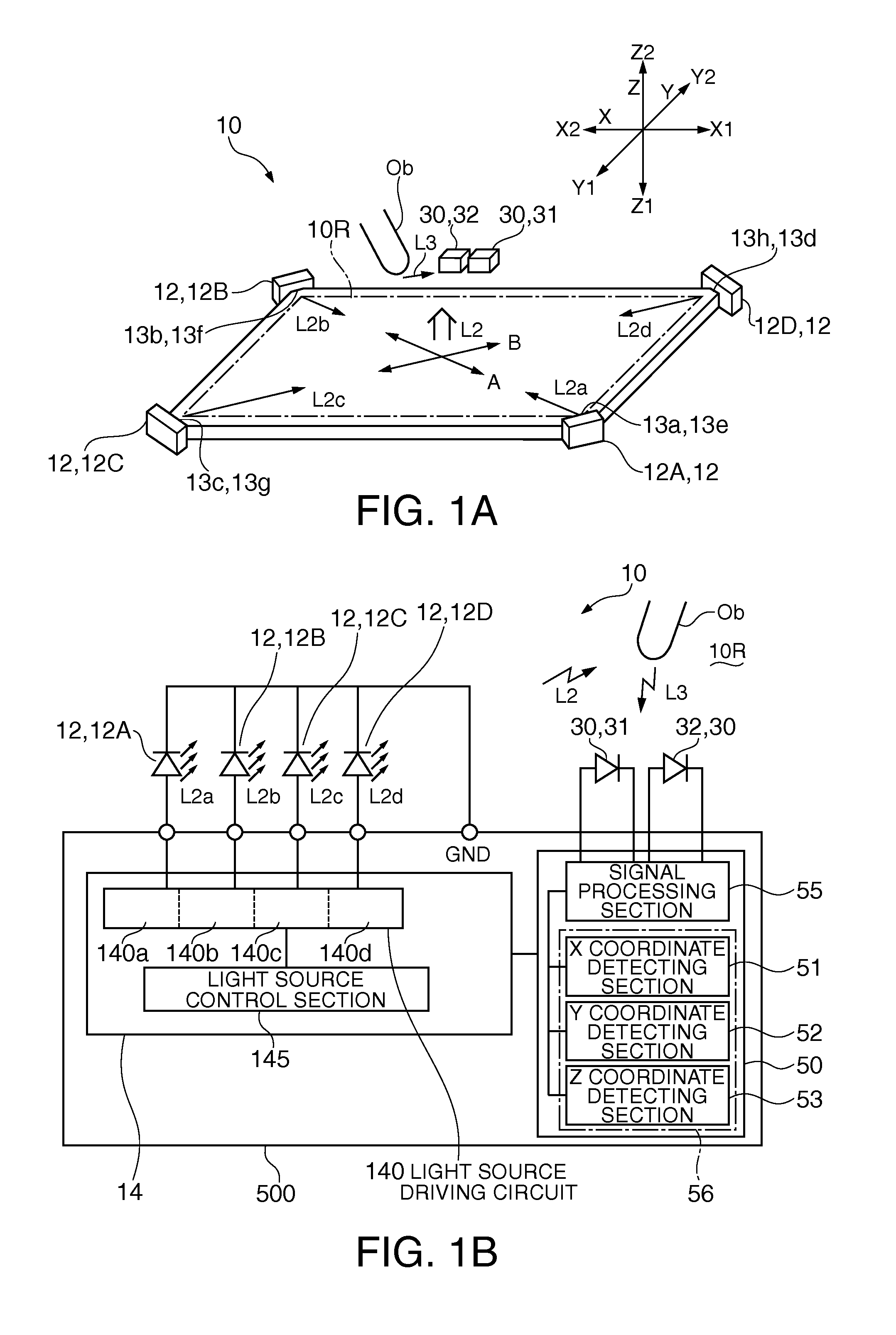
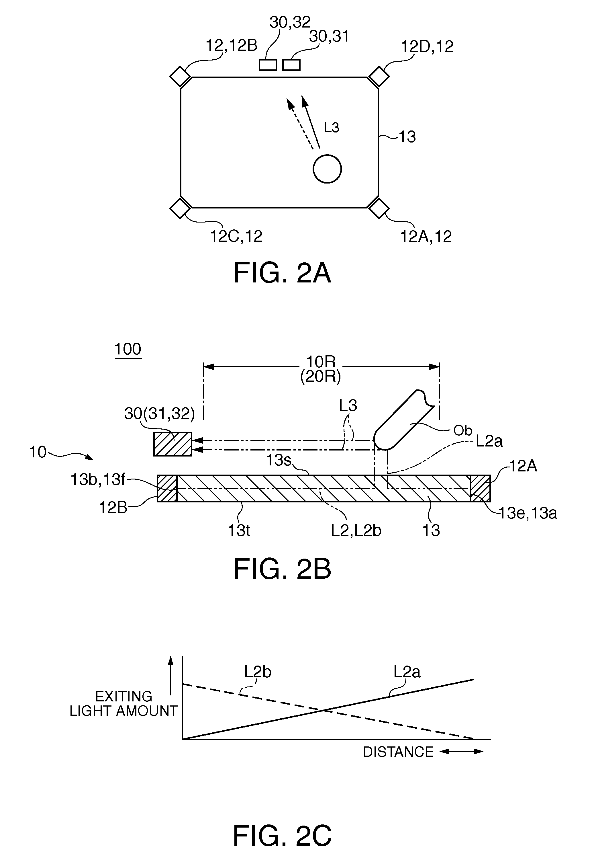
[0034]FIGS. 1A and 1B are diagrams illustrating main parts of an optical position detecting device according to a first embodiment of the invention, in which FIG. 1A is a diagram illustrating a layout of optical components used in the optical position detecting device, and FIG. 1B is a diagram illustrating an electric configuration of the optical position detecting device. FIGS. 2A, 2B and 2C are diagrams illustrating detection lights used in the optical position detecting device according to the first embodiment of the invention, in which FIG. 2A is a plan diagram illustrating a state where light reflected by a target object is received in a light detector, FIG. 2B is a cross-sectional diagram illustrating a state where light reflected by the target object is received in the light detector, and FIG. 2C is a diagram illustrating an attenuation state of a detection light in a light guiding plate.

[0035]As shown in FIG. 1A and F...

second embodiment

[0073]FIGS. 8A and 8B are diagrams illustrating main parts of the optical position detecting device 10 according to a second embodiment of the invention, in which FIG. 8A is a diagram illustrating a layout of optical components using the optical position detecting device 10, and FIG. 8B is a diagram illustrating an electric configuration of the optical position detecting device 10. Since the basic configuration of this embodiment is the same as that of the first embodiment, the same reference numerals are given to the same parts, and thus, description thereof will be omitted.

[0074]As shown in FIGS. 8A and 8B, the optical position detecting device 10 according to this embodiment includes a plurality of detection light sources 12 (detection light sources 12A to 12D) which emits a detection light L2, and light detectors 30 which detect part of a detection light L3 which is reflected from a target object Ob in a detection space 10R (exiting space of the detection light L2), in the detec...


PUM


Abstract

An optical position detecting device includes: a plurality of detection light source sections which emits a detection light; a light source driving section which turns on a part of the plurality of detection light source sections in a first period, and turns on the other part thereof in a second period; a first light detecting section which detects the detection light reflected by a object; a second light detecting section which has a sensitivity peak in a wavelength band which is different from that of the first light detecting section and detects the detection light reflected by the object; and a position detecting section which detects the position of the object on the basis of the intensity of the detection light in the first light detecting section and the intensity of the detection light in the second light detecting section in the first and second periods.

Description

BACKGROUND[0001]1. Technical Field[0002]The present invention relates an optical position detecting device which optically detects the position of a target object, and a display device with a position detecting function having the same.[0003]2. Related Art[0004]As an optical position detecting device which optically detects the position of a target object, a technique has been proposed which detects a position when light emitted from a light projection means is blocked by an indicating device and detects the light emitted from the indicating device to thereby detect the position of the indicating device (refer to JP-A-2005-173684).[0005]However, in the case of the technique of using the light emitted from the indicating device, since input through a finger, hand or the like is not possible, its usage is limited.[0006]Accordingly, as schematically shown in FIG. 14, the inventor has studied an optical position detecting device in which a detection light source 12 is disposed to face a...

Claims


Application Information

Patent Timeline
Patent Type & Authority Patents(United States)
IPC IPC(8): G09G5/00
CPCG06F3/0428
Inventor YOSHIDA, KAZUKI
Owner COLUMBIA PEAK VENTURES LLC
Features
  • R&D
  • Intellectual Property
  • Life Sciences
  • Materials
  • Tech Scout
  • Unparalleled Data Quality
  • Higher Quality Content
  • 60% Fewer Hallucinations
Learn More