Distributed remote base station system

a remote base station and distribution technology, applied in the field of distribution, can solve the problems of increased latencies of unacceptable disruption of services for some users of the system,

Active Publication Date: 2013-11-12
PROCOMM INT PTE LTD
View PDF262 Cites 86 Cited by
  • Summary
  • Abstract
  • Description
  • Claims
  • Application Information

AI Technical Summary

Benefits of technology

[0005]The above-mentioned problems of current systems are addressed by embodiments of the present invention and will be understood by reading and studying the following specification. The following summary is made by way of example and not by way of limitation. It is merely provided to aid the reader in understandi...

Problems solved by technology

This causes unneeded transmission of signals and results in increased latencies for use...

Method used


Image

  • Distributed remote base station system
  • Distributed remote base station system
  • Distributed remote base station system

Examples


Embodiment Construction

[0017]In the following detailed description, reference is made to the accompanying drawings that form a part hereof, and in which is shown by way of illustration specific illustrative embodiments in which the device may be practiced. These embodiments are described in sufficient detail to enable those skilled in the art to practice the invention, and it is to be understood that other embodiments may be utilized and that logical, mechanical and electrical changes may be made without departing from the spirit and scope of the present invention. The following detailed description is, therefore, not to be taken in a limiting sense.

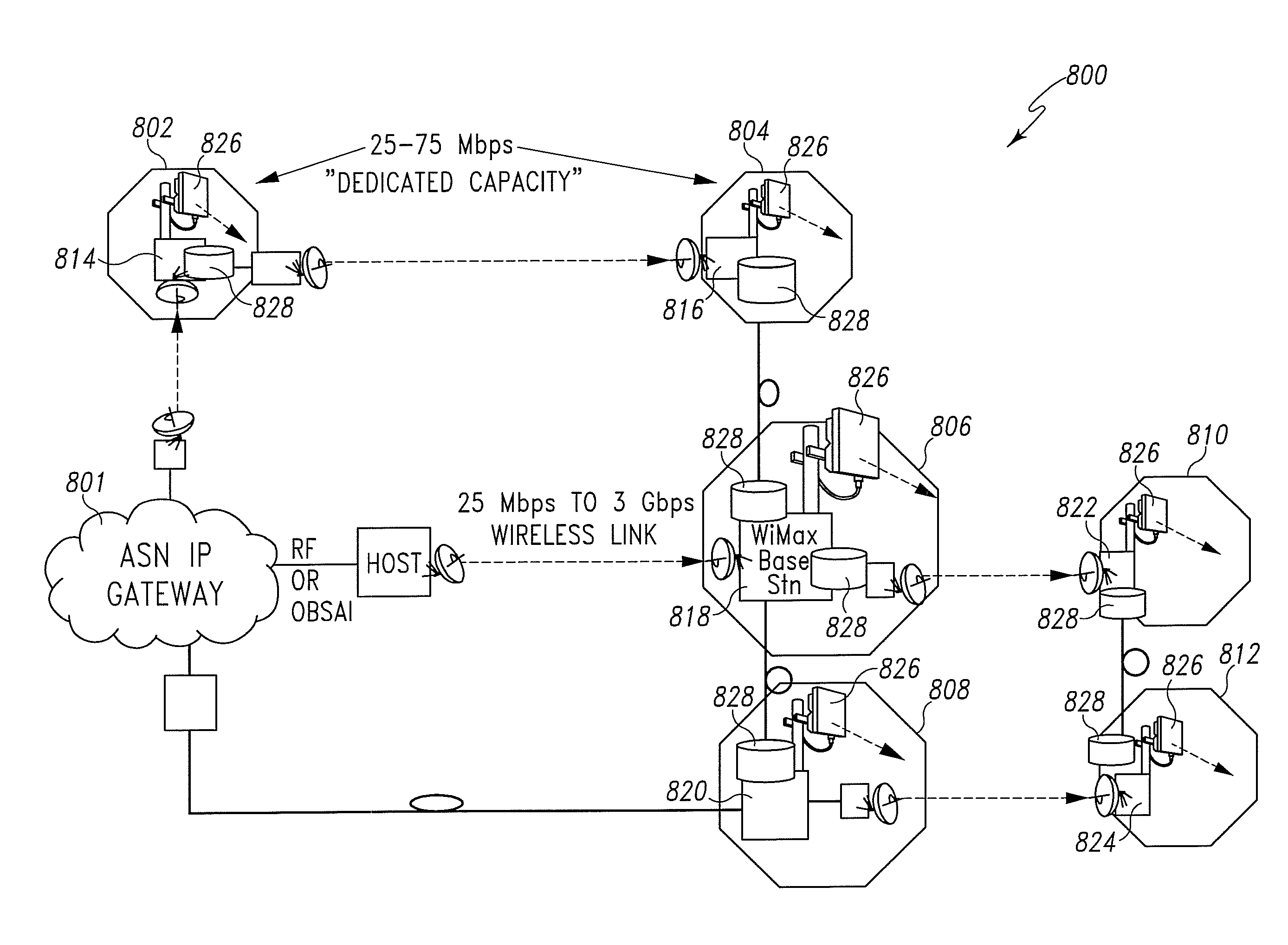
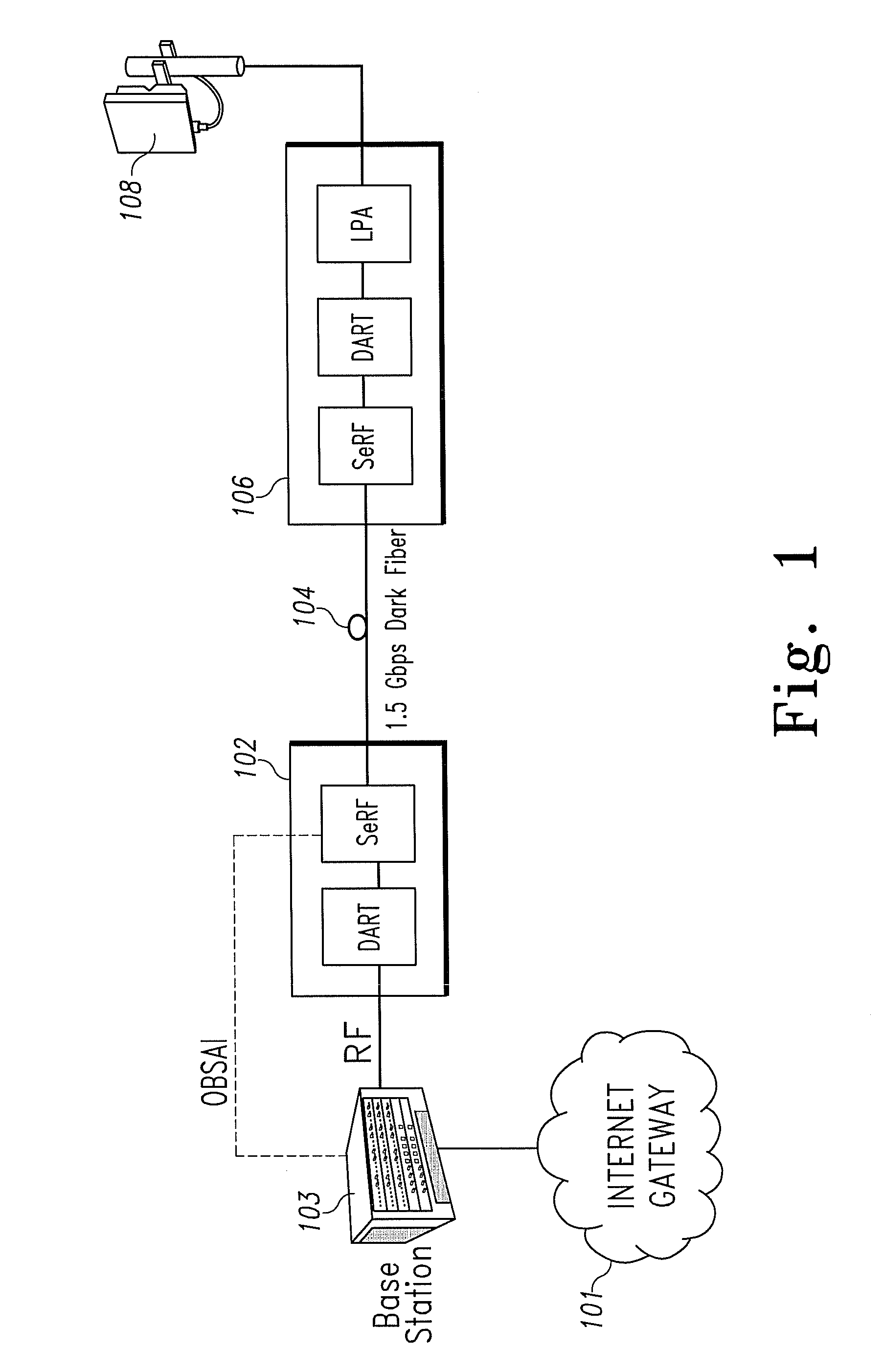
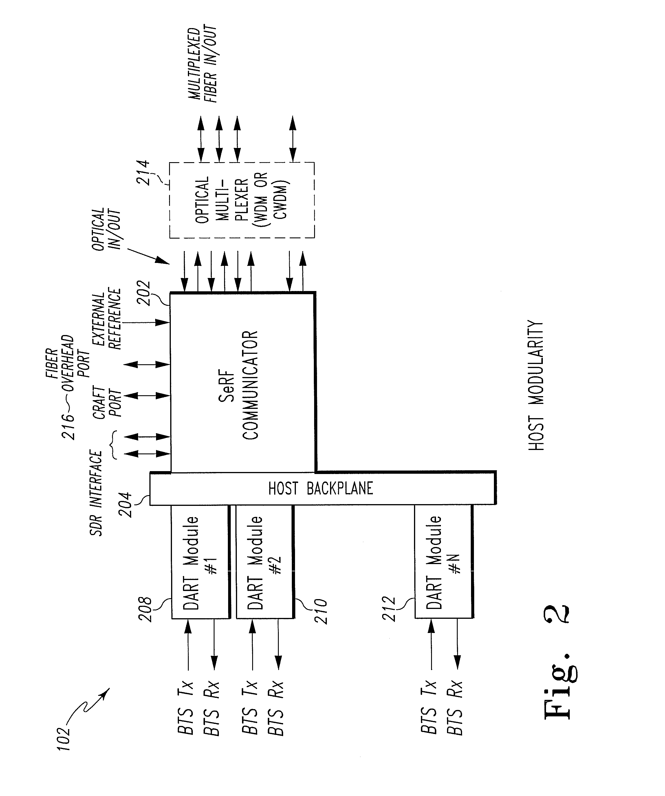
[0018]The present apparatus is a modular wireless platform that enables a system facilitator to easily and inexpensively adapt their wireless system for use with different data transport mechanisms, frequency bands, communication technologies, and intelligence distribution. This modular platform is made up of a reconfigurable host unit and a reconfigurable rem...


PUM


Abstract

A distributed base station system for high speed data transmission is disclosed. The system includes a plurality of remote antennas, each antenna being coupled to a router. The plurality of remote antennas is coupled to each other and is arranged into a network.

Description

RELATED APPLICATIONS[0001]This application is related to the following commonly assigned applications filed on even date herewith, each of which is hereby incorporated herein by reference:[0002]U.S. patent application Ser. No. 11 / 627,251 , entitled “MODULAR WIRELESS COMMUNICATIONS PLATFORM” (the '828 Application).BACKGROUND[0003]Traditional wireless communication systems may have distributed antennas to expand the range of a centralized base station. Any signals received by the distributed antennas must be sent back to the centralized base station for processing regardless of where the ultimate destination of the signal is located. This causes unneeded transmission of signals and results in increased latencies for users of the system. Additionally, each remote antenna is required to share capacity with every other antenna connected to the centralized base station. This causes unacceptable disruption of services for some users of the system.[0004]For the reasons stated above, and for...

Claims


Application Information

Patent Timeline
IPC IPC(8): H04W4/00H04W88/08
CPCH04W88/085
Inventor KOZIY, ROBERT J.ROBERTS, HAROLD A.SCHIEFFERT, TODD
Owner PROCOMM INT PTE LTD
Why Eureka
Try Eureka