Accessory bracket for firearm mount

a technology for accessorizing brackets and firearms, which is applied in the field of accessorizing brackets for firearm mounts, can solve the problems of not being able to fully move the firearm, not being able to meet the current armor configuration, and greatly reducing the ability of the operator to use the devi

Inactive Publication Date: 2013-11-19
STEINER EOPTICS INC
View PDF6 Cites 6 Cited by
  • Summary
  • Abstract
  • Description
  • Claims
  • Application Information

AI Technical Summary

Benefits of technology

[0004]The present invention provides a means for attaching an accessory bracket and accessories with the firearm mount wherein the means for attaching the accessory bracket further provides a means for adjusting the height of the accessory bracket in relation to the firearm mount, or the firearm and allows for independent interchange of multiple types of firearms. The accessory bracket provides a means for extension of the accessories for operator vision and full vertical movement of the firearm with firearm mount and armor shield independent of the length of the firearm; provides a means for safety when a firearm barrel or muzzle flash are shorter than the length of the accessory bracket; and provides a means for barrel change out without removal of the firearm or the accessory bracket from the firearm mount.
[0005]It is therefore an aim of the present invention to provide an accessory mount that is secured directly to the machine gun or firearm mount that will enable multiple firearms interchangeability and one to three accessory items for each firearm configuration.
[0006]It is another aim of the present invention to provide an accessory mount that accurately adjusts position and securely attaches without hindering firearm configurations.
[0007]It is a further aim of the present invention to provide an accessory mount that enables at least seven different firearms to be used interchangeably without modification of the firearm, weapon mount, or accessory bracket.
[0008]Therefore, in accordance with the present invention, there is provided an accessory mount for securing one to three accessories to the bracket, without compromise to the firearms or the weapon mount. The first element of the accessory mount is connected directly to the front of the weapon mount and the second element of the accessory mount is directly connected with the first element of the accessory mount. The second element of the accessory mount is adjustable and removable to accommodate the firearms installation or installation of firearm direct accessories. The second element has non-removable safety devices in order to minimize risk to the operator during firing operations. The second element of the accessory mount has design features that accommodate the larger firearms quick change barrel system without modification or change to the firearm or accessory mount. Also in accordance with the present invention, there is provided an accessory mount for use with current armor configurations in the field. The second element of the accessory mount extends well beyond the opening of the armor, which enables one to three accessory items to be mounted without modification of the firearm or the weapon mount. The accessory mount may provide electrical cables routing and relief to eliminate cable damage and to minimize the risk of electrical shock to the operator.

Problems solved by technology

A disadvantage of such mounts is that it is not compatible with the current armor configurations and will not allow full movement of the firearm through the armor shield due to the accessory and armor restricting firearm movement.
Without full firearm deflection, the ability of the operator to use the device is greatly reduced by not being able to direct the weapon as desired to neutralize enemy attacks at the limits of deflection.

Method used


Image

  • Accessory bracket for firearm mount
  • Accessory bracket for firearm mount
  • Accessory bracket for firearm mount

Examples


Embodiment Construction

[0038]The present invention relates to the general field of firearms. More specifically systems for mounting various accessories to firearms. The following description is presented to enable one of ordinary skill in the art to make and use the invention and to incorporate it in the context of particular applications. Various modifications, as well as a variety of uses in different applications will be readily apparent to those skilled in the art, and the general principles defined herein may be applied to a wide range of embodiments. Thus, the present invention is not intended to be limited to the embodiments presented, but is to be accorded the widest scope consistent with the principles and novel features disclosed herein.

[0039]Overview:

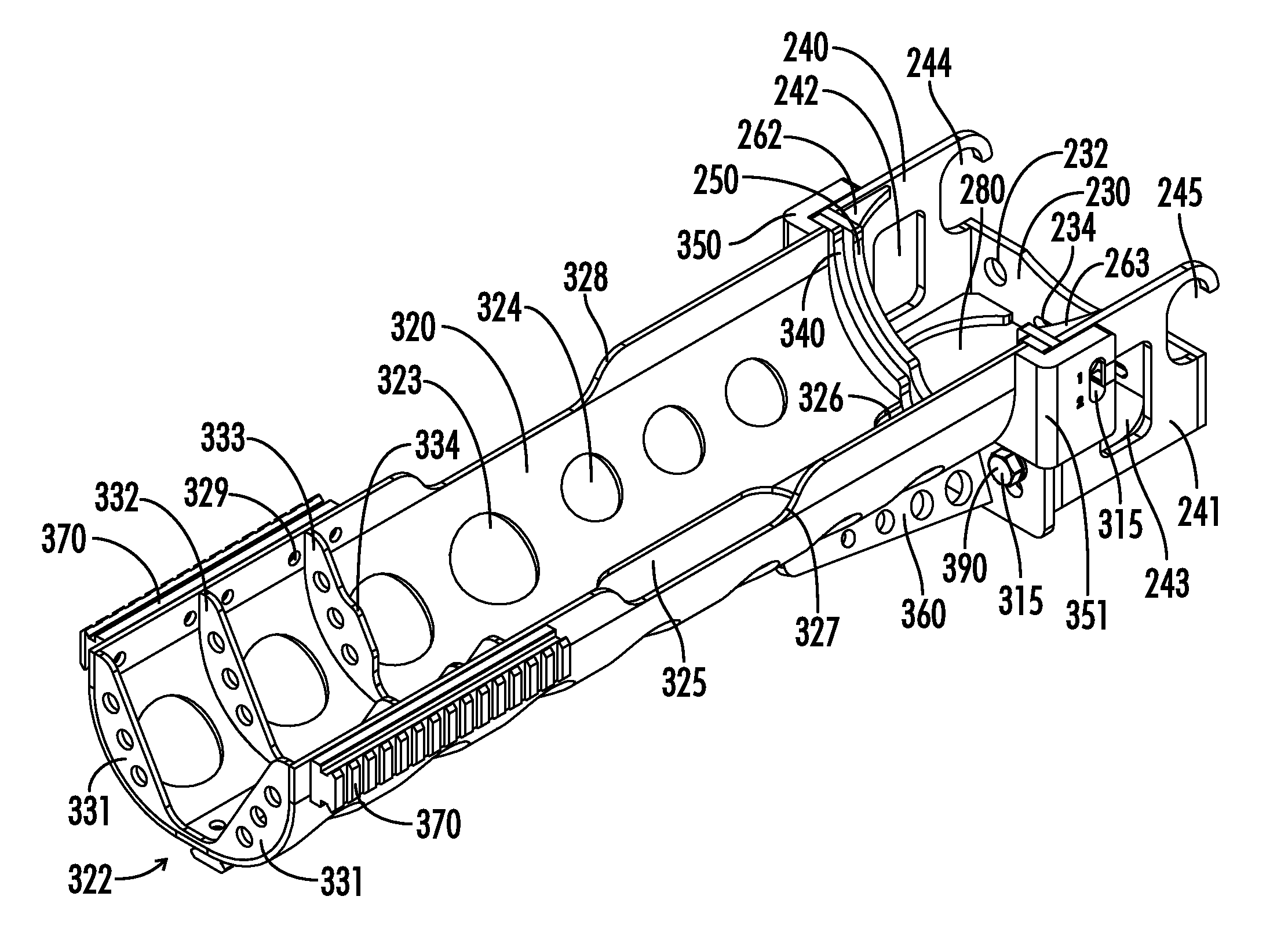
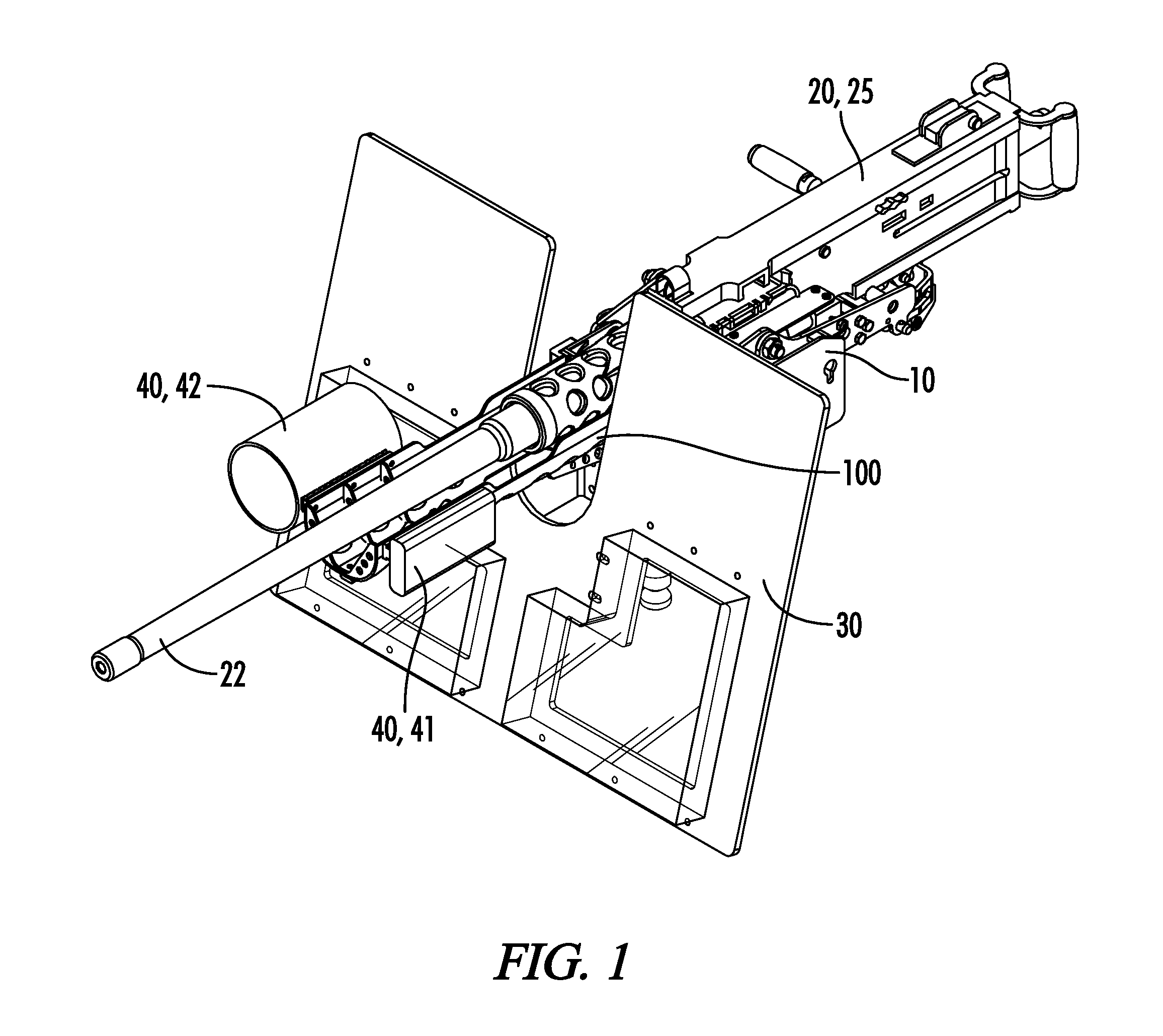
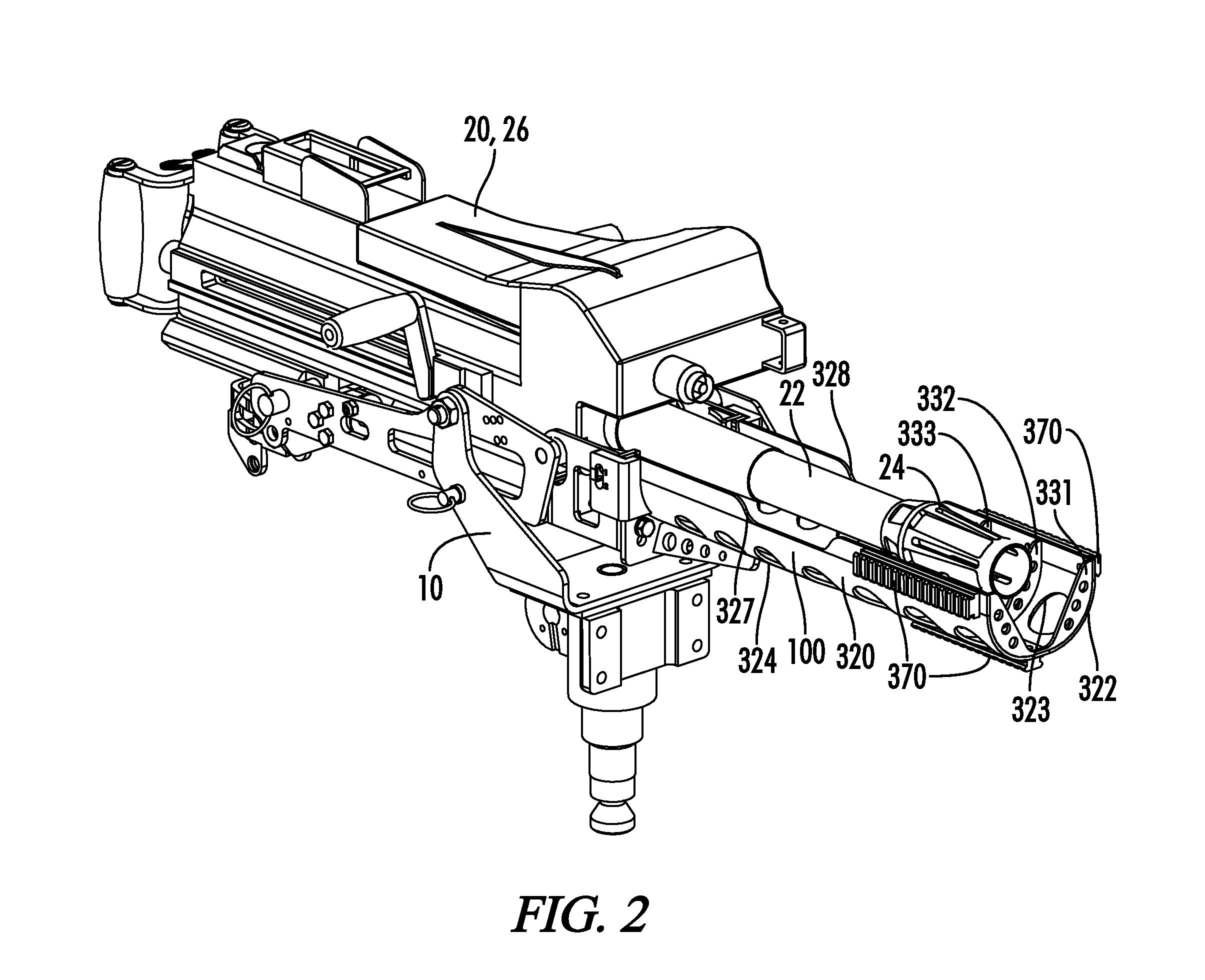
[0040]The function and utility of an accessory bracket is to attach the accessory bracket with a firearm mount or gun mount such as a MK-93 Gun Mount that receives multiple firearms including but not limited to heavy M2HB Machine Gun or MK19 Grenad...


PUM


Abstract

An accessory bracket 100 comprising first element 200 and second element 300 along with means for attaching first element with a firearm mount 10 and second element. The second element provides a semi-cylindrical accessory bar 320 with a length to safely extend the accessories such that the accessories do not interfere with operator vision or full movement or deflection of firearms. When attaching the second element with the first element, the accessory bracket provides an upper and lower position for adjusting the height of the second element in relation to the first element, the firearm mount, and the firearm 20. Safe, interchangeability for multiple firearms and accessories are provided as well as access areas and apertures for attaching the first and second elements, changing a barrel, wiring and connectors for accessories, as well as for firearm cooling and dispersal of gas and debris from the firearm rounds of ammunitions.

Description

FIELD OF INVENTION[0001]The present invention relates to the general field of firearms. It is specifically related to systems for mounting various accessories to firearms.BACKGROUND OF INVENTION[0002]It is well known to use various accessories such as infrared lasers, night vision optics and flood lights with firearms. In the case of small to large firearms the accessories may be securely mounted directly with the firearm or to an accessory bracket mounted directly with the firearm weapon. Small arms are known for the direct mounting configuration. The larger firearms such as the M2HB Machine Gun or the MK19 Grenade Launcher that produce much higher loads of recoil should be mounted with a weapon mount. Various accessories typically are mounted with the small firearm directly or in some cases the various accessories are mounted with an accessory rail or bracket that is directly mounted with the firearm. The larger machine gun firearm is normally placed into a machine gun mount for f...

Claims


Application Information

Patent Timeline
Patent Type & Authority Patents(United States)
IPC IPC(8): F41G3/06
CPCF41C27/00
Inventor MCCRIMMON, JR., THOMAS WARRENHAGEDORN, MARK EDWARDBEBEE, JOSEPH LADON
Owner STEINER EOPTICS INC
Why Eureka
Try Eureka