Driving position adjusting device for automotive vehicle
a technology for driving position and vehicle, which is applied in the direction of mechanical control devices, process and machine control, instruments, etc., can solve the problems of inability to properly adjust the driving operation system, the position of the pedal or the floor disposed near the pedal, and the inability to properly adjust the driving position
- Summary
- Abstract
- Description
- Claims
- Application Information
AI Technical Summary
Benefits of technology
Problems solved by technology
Method used
Image
Examples
modified example 1
[0095][Modified Example 1]
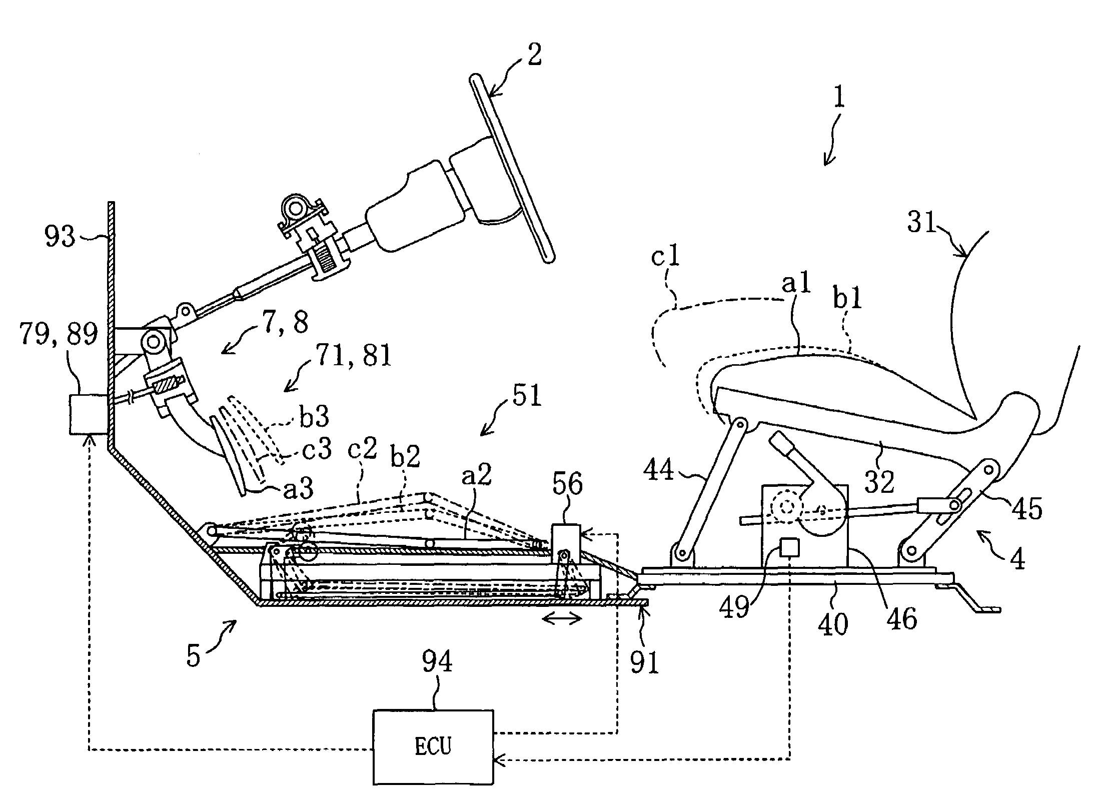
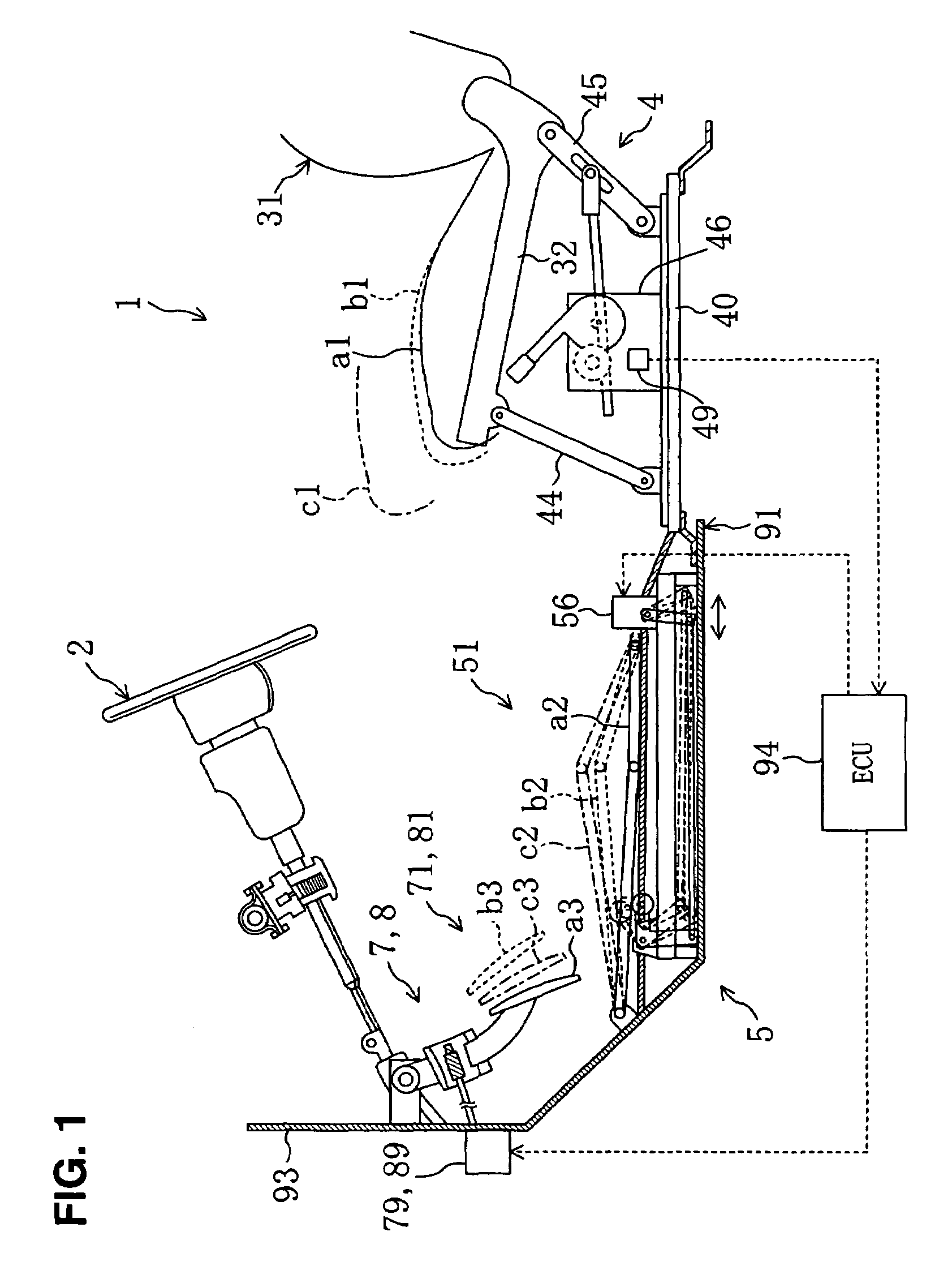
[0096]The turnover type of adjusting characteristic may be applied to the second adjusting characteristic for the movable floor 51. Namely, as shown in FIG. 11A, the seat-floor map is basically set such that the going-up-and-down position of the movable floor 51 has the substantially liner relationship with the seat position (the first adjusting characteristic). Meanwhile, the seat-floor map is set such that the going-up-and-down position of the movable floor 51 becomes lower as the seat position is located forward (the second adjusting characteristic) when the seat position is located before the specified seat position (M3). Accordingly, the ECU 94 controls the floor motor 56 such that the going-up-and-down position of the movable floor 51 becomes higher as the seat position is located forward, in other wards, as the driver's body size becomes small. When the seat position is located before the specified seat position (M3), the floor motor 56 is controlled...
modified example 2
[0100][Modified Example 2]
[0101]The second adjusting characteristic for the movable floor 51 may also be set such the going-up-and-down position of the movable floor does not change substantially according to the seat position's change (hereinafter, referred to as “the prohibition type”), as shown in FIG. 13A. Likewise, the second adjusting characteristic for the pedals 71 and 81 may be set at this prohibition type in which the arrangement positions of the pedals 71 and 81 do not change substantially according to the seat position's change, as shown in FIGS. 13B and 13C.
modified example 3
[0102][Modified Example 3]
[0103]The above-described pedals 71 and 81 and the movable floor 51 are adjusted by the motors 56, 79 and 89 electrically controlled by the ECU 94 with the function of secondary degree with respect to the seat position. However, these adjusting may be conducted with the linear function (function of the first degree) with respect to the seat position as shown in FIGS. 14A, 14B and 14C. Specifically, FIG. 14A shows the restraint type of adjusting characteristic in which the adjusting amount is restrained when the driver's body size is smaller than the specified size. FIG. 14B shows the turnover type of adjusting characteristic in which the adjusting direction is turned over when the driver's body size is smaller than the specified size. FIG. 14C shows the prohibition type of adjusting characteristic in which the adjusting is prohibited when the driver's body size is smaller than the specified size.
[0104]The above-described adjusting characteristics enables a ...
PUM
 Abstract
Description
Claims
Application Information
 - R&D
- Intellectual Property
- Life Sciences
- Materials
- Tech Scout
- Unparalleled Data Quality
- Higher Quality Content
- 60% Fewer Hallucinations
Browse by: Latest US Patents, China's latest patents, Technical Efficacy Thesaurus, Application Domain, Technology Topic, Popular Technical Reports.
© 2025 PatSnap. All rights reserved.Legal|Privacy policy|Modern Slavery Act Transparency Statement|Sitemap|About US| Contact US: help@patsnap.com


